
Starting large induction and synchronous motors on weak power systems creates high inrush currents that depress system voltage and threaten grid stability. VarStec’s MotorVAR is a system-fit, medium-voltage capacitor bank designed to provide precise, transient-free reactive power locally at the motor bus during the starting cycle. By supplying the necessary magnetizing vars at the point of use, MotorVAR preserves available starting torque and reduces voltage sag without the cost, harmonic distortion, or maintenance complexity of VFD or RVSS systems. This page answers frequently asked technical questions about MotorVAR sizing, motor torque support during starting, and the engineering calculations used to evaluate motor-starting performance.
Motor Starting & Voltage Sag Technical Q&A
Motor starting torque is approximately proportional to the square of the motor terminal voltage (Torque ∝ V²). This creates a fundamental limitation for traditional reduced-voltage starting methods. A line reactor reduces starting current by inserting impedance in series with the motor, while an RVSS reduces or limits the voltage applied to the motor. In both cases, lower motor current is achieved at least partly by reducing motor terminal voltage—and the resulting reduction in starting torque can be substantial.
For example, reducing motor terminal voltage to 70% of rated voltage reduces the available starting torque to approximately 49% of the across-the-line value. At 50% voltage, only about 25% of starting torque remains. A starter can therefore successfully limit current and reduce voltage sag on the upstream system while simultaneously leaving the motor with insufficient torque to accelerate the driven load.
MotorVAR approaches the problem differently. Rather than relying solely on series impedance or reduced motor voltage, MotorVAR connects a switched source of reactive power at or near the motor bus during acceleration. The capacitors supply a portion of the motor’s large reactive starting requirement locally, reducing the reactive current that must be supplied through the transformer and upstream power system. The resulting reduction in system voltage drop allows the motor terminal voltage to remain higher and therefore preserves substantially more starting torque.
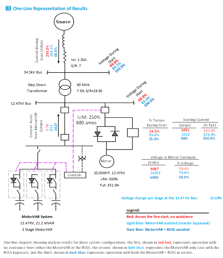
This distinction becomes particularly important on weak electrical systems. An RVSS or reactor may reduce the current seen by the source, but if the resulting motor voltage is too low, the motor may accelerate slowly, stall, or fail to start altogether. MotorVAR can often be added to an existing RVSS or reactor-start installation to provide the additional voltage support needed to complete the start. In many cases, this provides a practical solution when a reduced-voltage starter has already been installed and commissioning tests reveal that adequate starting torque is not available.
MotorVAR can also be intentionally coordinated with an RVSS or reactor start system from the beginning of the design. The reduced-voltage starter limits motor current, while MotorVAR supplies local reactive power and supports the system voltage. Because the starter (RVSS or Reactor start system) is already reducing the motor’s electrical demand, the required MotorVAR rating can often be smaller than would be required for a MotorVAR-only assisted start. The design can therefore be optimized around three competing objectives: motor starting torque, allowable system voltage sag, and upstream starting current.
The performance comparison shown in the example below illustrates this tradeoff. A MotorVAR-only start can provide substantially greater motor terminal voltage and starting torque than an unassisted start, while a coordinated MotorVAR + RVSS arrangement can further reduce the current and voltage disturbance imposed on the upstream electrical system. The appropriate configuration depends on the acceleration torque required by the driven load and the electrical limitations of the supplying system.
VarStec Perspective
A common motor-starting problem is discovered after the equipment has already been installed: the RVSS or reactor performs exactly as intended in limiting current, but the resulting motor terminal voltage is too low to produce enough torque to accelerate the load. Replacing the starter is not necessarily the best solution. The existing equipment can often remain in service, with MotorVAR added as a coordinated voltage-support system to provide the additional starting capability that is missing.
VarStec’s MotorVAR™ Sizing Tool evaluates these alternatives before equipment is selected, or can be used to investigate a motor that is having difficulty starting in the field. The tool calculates and compares the performance of:
- Unassisted / across-the-line starting
- MotorVAR-only assisted starting
- MotorVAR + RVSS assisted starting
- MotorVAR coordinated with reactor starting
- MotorVAR + captive transfomer start
For each configuration, the analysis evaluates motor terminal voltage, available starting torque, upstream current, and voltage performance at critical system buses. This allows the MotorVAR rating and starter settings to be selected together rather than treating motor starting current, voltage sag, and accelerating torque as separate problems.
This is one of the key advantages of capacitor-assisted motor starting.
During starting, a large induction motor requires substantial reactive current. Without local compensation, that reactive current must flow through the utility source, transformer, cables, and other upstream equipment. The resulting current produces voltage drop across the system impedance.
MotorVAR supplies a portion (some or all) of that reactive current locally at the motor bus. The upstream source therefore supplies less of the motor’s reactive requirement, reducing the current flowing through the transformer and utility system.
At the same time, the improved motor-bus voltage allows the motor to draw the current it needs and develop greater starting torque. Therefore, motor-terminal current can increase while the current seen by the upstream power system decreases.
The voltage sag produced by a motor start depends heavily on the impedance between the utility source and the motor. A lower utility short-circuit level, higher transformer impedance, or combination of the two creates a weaker electrical source and generally results in greater voltage depression for a given motor-starting current.
For this reason, the MotorVAR sizing process models the utility source impedance and transformer impedance rather than evaluating the motor independently. The resulting voltage is checked at multiple locations, including the motor or secondary bus and the upstream point of common coupling (PCC).
This is why the same motor may start acceptably on one power system but require substantial reactive-power support on another.
Motor-starting performance should not be evaluated based on motor-terminal voltage alone. The starting event can affect several voltage levels within the electrical system.
VarStec’s MotorVAR sizing analysis evaluates, as applicable:
- Motor terminal voltage
- Main secondary or motor-bus voltage
- Transformer primary voltage
- Point of common coupling (PCC) voltage
The MotorVAR Sizing Tool uses typical screening objectives of approximately 90% of nominal voltage at the secondary bus and 96% at the primary bus, while also evaluating the voltage available directly at the motor.
Actual allowable voltage sag should ultimately be based on the project requirements, utility criteria, connected-process sensitivity, and the motor’s torque requirements.
Proper MotorVAR™ sizing requires more than the motor horsepower and voltage. The starting performance depends on the electrical strength of the entire system between the utility source and the motor.
VarStec typically evaluates:
- Utility source: PCC voltage, three-phase short-circuit current, and X/R ratio.
- Step-down transformer: MVA rating, primary and secondary voltage, percent leakage impedance, and X/R ratio.
- Motor: rated voltage, horsepower, full-load current (FLA), full-load power factor and efficiency, locked-rotor current (LRA), and locked-rotor power factor.
- MotorVAR™ system: capacitor-bank voltage rating, total reactive power rating, and number of stages.
- Additional starting equipment, when applicable: line-reactor impedance, RVSS current-limit setting, or captive-transformer data.
These parameters allow the system impedances, motor starting current, bus voltages, starting torque, upstream current, and required MotorVAR™ reactive-power support to be evaluated together.
Motor horsepower alone does not adequately define the electrical requirements of a motor start. Locked-rotor current establishes the magnitude of the starting current, while locked-rotor power factor determines how much of that current is active versus reactive.
The MotorVAR sizing calculation tool uses these values to establish the motor’s locked-rotor impedance and reactive-power demand during starting. Because MotorVAR™ primarily supplies the reactive component of the starting current locally, locked-rotor power factor can have a significant effect on the amount of capacitor support required.
As a result, two motors with the same horsepower and voltage can require substantially different MotorVAR ratings if their locked-rotor characteristics are different.
Determining the optimum capacitor size for a MotorVAR application is not a simple one-size-fits-all kvar selection. It requires evaluation of the motor, the connected load, and system and source impedance data. Using the MotorVAR Sizing Tool, VarStec engineers evaluate three primary criteria:
- Voltage Sag
The tool calculates the expected voltage at the motor bus, main plant bus, and point of common coupling (PCC) to confirm acceptable system performance during motor starting.
- Motor Bus Voltage: Confirms that the motor maintains adequate voltage during starting to develop the required torque. This value is typically evaluated at 85% to 90% of nominal system voltage.
- Main Plant Bus Voltage: Confirms that plant voltage remains within acceptable power quality limits during starting. This value is typically 90% of nominal or better.
- PCC Voltage: Confirms that voltage sag at the utility interconnection meets applicable interconnect requirements. This value is typically 96% of nominal.
- System Inrush Current
The tool calculates the net current drawn from the upstream source so the MotorVAR can be sized to reduce inrush current and help keep the starting event within utility or system interconnect requirements. - Motor Starting Torque
The tool calculates the electrical torque available during motor starting. This value must then be compared against the connected load torque requirement to verify adequate accelerating torque.. VarStec typically recommends maintaining a torque margin of at least 50%.
A large motor may require substantial reactive-power support at the beginning of the starting cycle, but that requirement changes as the motor accelerates. Dividing the MotorVAR into multiple stages allows the reactive-power support to be controlled in increments rather than switching the entire capacitor rating as a single block. Proper staging helps maintain the required motor and system voltage while limiting voltage fluctuations during acceleration. Initial stage removal is based on measured system voltage, with subsequent stages removed using application-specific timing established from the motor and load inertia and the electrical-system characteristics. No motor-start confirmation signal or bidirectional start-confirmation handshake is required. The number and size of the stages are therefore part of the MotorVAR engineering analysis and should be coordinated with the motor, system short-circuit strength, total capacitor rating, and switching sequence.
No. The MotorVAR Sizing Tool is intended for preliminary engineering, feasibility assessment, comparative analysis, and initial system sizing.
It provides a practical method for evaluating the relationship between source strength, transformer impedance, motor locked-rotor characteristics, capacitor-bank size, motor voltage, starting torque, upstream current, and system voltage sag.
Final MotorVAR configuration, capacitor staging, switching sequence, protection coordination, and motor acceleration performance should be confirmed through a detailed engineering review and, where appropriate, a dynamic motor-starting study using the motor torque-speed and driven-load characteristics. The study also establishes the application-specific stage-removal timing used after the initial voltage-based stage removal.
Yes. In some severe applications where the system is exceptionally weak, the VarStec MotorVAR + Line Reactor configuration is utilized. In this scheme, the MotorVAR capacitor is connected to the secondary bus while a line reactor is inserted in series with the motor.
The sizing tool models this combined impedance of the motor and the reactor (ZT=ZM+ZR) in parallel with the capacitor’s capacitive reactance (ZC). This “Hybrid” approach allows for maximum inrush current limitation at the source while using the capacitor to “boost” the voltage at the reactor’s line-side, ensuring the motor still receives enough voltage to accelerate the load successfully.
Yes. For difficult motor-starting applications, MotorVAR and an RVSS can be coordinated as a combined starting system.
The MotorVAR supplies reactive power locally to support motor and system voltage, while the RVSS limits motor current. The combination can further reduce the disturbance seen by the upstream system compared with MotorVAR™ alone.
There is, however, an important tradeoff. Increasing the amount of RVSS current limiting also reduces the current delivered to the motor and therefore reduces available starting torque. The RVSS current-limit setting must consequently be selected together with the MotorVAR rating so that improved system-voltage performance does not prevent the motor from developing sufficient torque to accelerate the connected load.
Additionally, because the RVSS puts out harmonics, the MotorVAR must use detuned capacitor stages as its starting capacitor elements.
Yes. MotorVAR™ can be evaluated for applications in which the motor is supplied through a dedicated or captive transformer.
In these systems, the captive transformer’s voltage ratio and leakage impedance become additional elements of the motor-starting circuit. VarStec evaluates the voltage at the motor bus, the captive-transformer primary, the upstream secondary bus, and the PCC to determine how the motor start propagates through the electrical system.
This configuration is modeled in VarStec’s MotorVar Medium-Voltage Motor Starting Sizing & Analysis Tool and can be particularly important for large lower-voltage motors supplied from medium-voltage distribution systems, where both the captive transformer and the upstream transformer contribute to the total source impedance seen by the motor.
MotorVAR is a viable alternative to a Variable Frequency Drive (VFD) for motor starting when the motor is intended to run at full speed and only requires reactive power support during the starting event. In these applications, the engineering problem is not variable speed control, but maintaining sufficient motor terminal voltage and starting torque while limiting upstream voltage sag and source current. MotorVAR™ addresses that problem directly by supplying local reactive power at the motor bus during starting, allowing the motor to start successfully across the line without the added complexity of a medium-voltage drive system.
Compared with a VFD-based starting solution, MotorVAR offers several practical advantages in fixed-speed applications:
- Lower installed complexity: MotorVAR avoids the bypass switchgear, synchronization logic, and associated control complexity often required with VFD-based motor starting systems.
- No steady-state harmonic source: MotorVAR does not introduce the characteristic harmonics associated with variable speed drives.
- No power-electronic dependence: The system is based on conventional medium-voltage capacitor bank technology rather than large proprietary drive assemblies.
- No dedicated drive enclosure requirement: MotorVAR does not require the conditioned E-House space often associated with large medium-voltage drives.
- Standard maintainable components: The system uses conventional capacitors, fuses, relays, switching devices, and controls that plant personnel are generally familiar with and can maintain without factory drive specialists.
- Plant-wide starting coverage: A single MotorVAR system can be designed to support the starting of all large motors in a plant. This improves the economic case because one shared MotorVAR installation may replace multiple dedicated motor starting devices.
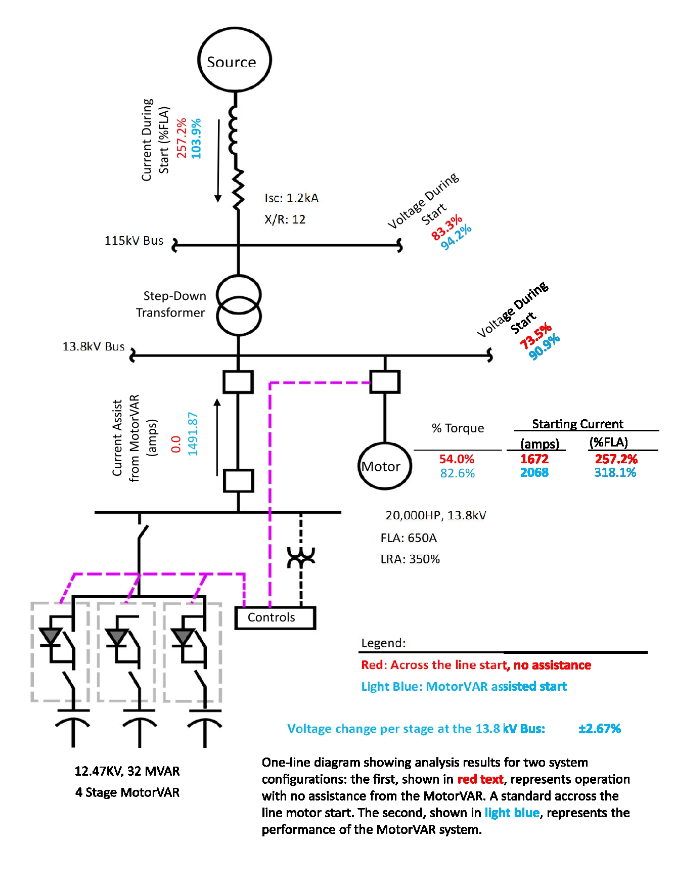
From an engineering standpoint, MotorVAR is most attractive where variable-speed operation is not required and the primary objective is to start a large motor successfully on a weak power system using the simplest practical medium-voltage solution. The figure below illustrates the improvement in motor-starting performance. The red data represents an across-the-line start, while the blue data represents the same motor start with MotorVAR™ applied. In this example, a 32 MVAR MotorVAR system increases the starting voltage of a 20,000 HP motor from 73.5% to 90.9%, clearly demonstrating the effectiveness of capacitor-assisted starting in reducing motor-starting voltage sag.
No. MotorVAR operates from the motor-start command and does not require a motor-start confirmation signal or bidirectional start-confirmation handshake. Once the start command is received, MotorVAR initiates the programmed capacitor-stage sequence. Initial stage removal is based on measured system voltage, with subsequent stages removed using application-specific timing established from the motor, load, and electrical-system characteristics.
No. MotorVAR does not determine successful completion of the motor-starting sequence based on confirmation of capacitor-switch closure. Equipment status, auxiliary contacts, alarms, and diagnostics may be used for protection, monitoring, maintenance, annunciation, and interlocking, but they are not used as motor-start confirmation or as the basis for determining whether the motor has successfully started.
MotorVAR includes an independent overvoltage protection relay or uses a relay element of the MotorVar controller that continuously monitors system voltage. Consistent with the protection practices of IEEE Std 1036, this function provides protection against overvoltage conditions that could adversely affect the MotorVAR capacitor bank, motor, or connected electrical system. If the programmed overvoltage threshold is exceeded before a start, MotorVAR operation is blocked. If the threshold is exceeded while MotorVAR is operating, the appropriate protective action is initiated to remove the capacitor stages. Overvoltage protection operates independently of motor-start status and is not used to determine or confirm whether the motor has successfully started.
Related Technical Topics
VarStec’s Engineering-Led Approach to MotorVAR™ Motor Starting
VarStec applies practical engineering experience to the design, sizing, and manufacture of MotorVAR™ medium-voltage motor starting systems for large fixed-speed motor applications. MotorVAR™ is a cost-effective alternative to VFD-based starting solutions when the engineering objective is to maintain motor terminal voltage, preserve starting torque, and limit upstream voltage sag without the added cost and complexity of medium-voltage drive systems. To support proper application, VarStec provides the MotorVAR Sizing Tool to help EPCs, consultants, and end users evaluate voltage sag, inrush current, and starting torque requirements for a given motor and power system. VarStec can also assist directly with the engineering review, sizing, and final design of the MotorVAR™ solution, delivering a System-Fit™ motor starting package engineered to meet the performance, reliability, and economic objectives of the project.