
Brief No.: VEB-011
Category: Equipment Design / Component Ratings / IEEE Standards / Switching Transients
Download the VarStec Engineering Brief: VEB-011 Evaluating Capacitor Switching Device Test Reports.
Abstract
Medium-voltage capacitor banks and harmonic filter banks rely on switching devices capable of repeatedly interrupting capacitive currents without restrike or excessive switching transients. Class C2 and BC2 ratings are commonly used to indicate very low restrike probability; however, identical classifications may be obtained through different test standards, test sequences, and device-specific requirements.
This paper examines the standards applicable to capacitor switches and circuit breakers, with emphasis on the differences in testing used to establish capacitive switching performance. A structured methodology is presented for reviewing manufacturer type-test reports, identifying the standard and test sequence applied, evaluating required preconditioning and switching duties, and determining whether the demonstrated performance is appropriate for the device and its intended application.
Index Terms – Capacitor banks, capacitor switching, circuit breakers, Class C2, BC2, harmonic filter banks, medium voltage, restrike, switching devices, switching transients, type testing.
I. INTRODUCTION
Medium-voltage capacitor banks and harmonic filter banks depend heavily on the performance of the device used to switch capacitive current. Unlike many components within the bank, the switching device is repeatedly subjected to transient recovery voltage, dielectric recovery stress, inrush and outrush current, and the possibility of restrike during interruption. Its performance therefore has a direct influence on the reliability and service life of the complete capacitor bank or harmonic filter bank.
Class C2 and BC2 ratings are widely used to identify switching devices having a very low probability of restrike. These classifications are frequently cited by manufacturers as evidence of superior capacitive switching performance and are often used by engineers, consultants, and equipment manufacturers when selecting preferred switching devices. The classification alone, however, does not describe the complete test program used to establish the rating. Circuit breakers and dedicated capacitor switches are fundamentally different devices and are subjected to different test sequences, preconditioning requirements, numbers of operations, and methods of establishing worst-case switching conditions.
For this reason, evaluation of a capacitor switching device should extend beyond the rating shown on a vendor’s data sheet. The reviewer should determine what the device is, which standard was applied, what test path was followed, what electrical and mechanical stresses were imposed during testing, and whether those tests are appropriate for the device being offered. A circuit breaker should first demonstrate compliance with the requirements applicable to circuit breakers, while a dedicated capacitor switch should demonstrate compliance with the requirements applicable to capacitor switches. Additional testing beyond the device’s primary standard can further demonstrate switching performance, but it should not replace the testing required for that type of device.
This Engineering Brief reviews the evolution of the principal IEEE standards governing medium-voltage capacitive switching and presents a structured method for auditing manufacturer type-test reports. Particular attention is given to the differences between circuit-breaker and dedicated capacitor-switch qualification, including short-circuit preconditioning, operation count, minimum-arcing-time testing, random switching requirements, point-on-wave control, allowable restrikes, and post-test condition. The objective is to provide engineers, EPCs, and consultants with a practical means of determining what a manufacturer’s published Class C2 or BC2 rating actually demonstrates.
II. WHY IT MATTERS
The switching device is one of the most critical components in a medium-voltage capacitor bank or harmonic filter bank. Its ability to repeatedly switch capacitive current with a very low probability of restrike has a direct influence on the reliability, performance, and service life of the entire capacitor bank or harmonic filter bank.
For that reason, a Class C2 or BC2 designation is most meaningful when considered together with the test program used to establish it. Understanding how the device earned that rating, and whether it was tested under requirements appropriate for the device being supplied, is an important part of evaluating both the switching device and the equipment in which it will be applied.
III. EVOLUTION OF IEEE CAPACITIVE SWITCHING STANDARDS
Capacitive current switching test procedures were historically fragmented across multiple independent standards. In recent years, the IEEE Switchgear Committee undertook a major restructuring effort to eliminate conflicting requirements and align North American rules with global testing practices.
Legacy Rating Tables Rolled into C37.04: IEEE Std C37.06-2009 (Preferred Ratings and Related Required Capabilities for AC High-Voltage Circuit Breakers) was officially withdrawn by the IEEE Standards Board. All preferred rating tables, including continuous current, short-circuit interrupting, and capacitive switching ratings, were consolidated directly into IEEE Std C37.04-2018. Modern project specifications referencing C37.06 should therefore be interpreted using the corresponding requirements of C37.04-2018.
Unified Capacitive Testing Wrapped into C37.100.2: In 2018, IEEE consolidated capacitive current switching test procedures that were previously scattered across legacy standards into a single overarching standard, IEEE Std C37.100.2-2018. This standard absorbed and superseded:
- IEEE Std C37.09a-2005 (Capacitance Current Switching Supplement to Circuit Breaker Test Procedures)
- IEEE Std C37.66-2005 (capacitor switch testing clauses)
- IEEE Std 1247-2005 (interrupter switch capacitive testing clauses)
A. Current Governing IEEE Standards
When auditing vendor test reports or updating client specifications, the following current editions of the IEEE standards should be referenced:
- IEEE Std C37.100.2-2018, IEEE Standard for Common Requirements for Testing of AC Capacitive Current Switching Devices over 1000 V (The primary test standard governing Class C0, C1, and C2 test duties).
- IEEE Std C37.04-2018, IEEE Standard for Ratings and Requirements for AC High-Voltage Circuit Breakers with Rated Maximum Voltage Above 1000 V (Defines circuit-breaker rating structures, preferred capacitive currents, and TRV capabilities).
- IEEE Std C37.09-2018 (with Corrigendum 1-2021), IEEE Standard Test Procedures for AC High-Voltage Circuit Breakers with Rated Maximum Voltage Above 1000 V (Governs circuit-breaker design test procedures, including mandatory T60 fault preconditioning).
- IEEE Std C37.66-2021, IEEE Standard Requirements for Capacitor Switches for AC Systems (1 kV to 38 kV) (Governs apparatus construction, continuous current, short-time withstand, and switch endurance).
- IEEE Std C37.012-2022, IEEE Guide for the Application of Capacitive Current Switching for AC High-Voltage Circuit Breakers Above 1000 V (Provides application physics, transient inrush/outrush calculations, (I × f) product limits, and TRV mitigation rules).
- IEEE Std 1036-2020, IEEE Guide for the Application of Shunt Power Capacitors (Governs shunt capacitor bank ratings, transient overvoltages, unbalance protection, and bank configuration limits).
B. IEEE/IEC Harmonization
A technical nuance when auditing international equipment manufacturers (e.g., ABB, Siemens, Schneider Electric) is the formal harmonization between IEEE and IEC testing frameworks. The 104-shot three-phase targeted test program used for Class C2 circuit breakers in IEEE Std C37.100.2-2018 was directly harmonized with IEC 62271-100:2021 (High-Voltage Switchgear and Controlgear – Part 100: Alternating-Current Circuit-Breakers).
Under Clause 4.12 (“Harmonization with IEC”) of IEEE Std C37.100.2-2018, devices that have been fully type-tested in accredited laboratories under IEC 62271-100 and achieved a Class C2 rating are explicitly recognized as compliant with IEEE capacitive switching requirements:
“Devices that are tested to IEC 62271-100 for capacitive switching and meeting Class C2 are acceptable to the requirements of this standard. Rating and application shall be stated when used in IEEE applications and the IEC test reports shall support the specified ratings.” – IEEE Std C37.100.2-2018, Clause 4.12
Audit Note: While an IEC 62271-100 Class C2 test certificate satisfies the capacitive switching requirements of IEEE C37.100.2 through Clause 4.12, other requirements, such as breaker construction, thermal continuous-current capability, and BIL insulation levels, may not fully align with North American IEEE C37.04/C37.09 requirements. For metal-enclosed capacitor banks and harmonic filter banks, however, these differences may be less significant because the equipment is typically custom-designed, switching devices are often applied well below their continuous-current ratings, and the devices are not necessarily installed in standardized breaker compartments.
It is VarStec’s position that, where these other differences are immaterial to the application, demonstrated switching performance and reliability should take precedence over whether the device nameplate references an IEEE or IEC standard. VarStec therefore favors the switching device that demonstrates the stronger performance for the intended duty, regardless of the standards organization under which that performance was qualified.
IV. CIRCUIT-BREAKER CLASS C2 (BC2) AUDIT
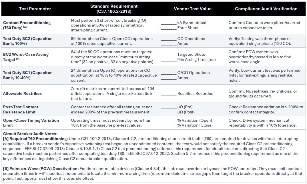
A circuit breaker is classified as a Time-Controllable Device under IEEE Std C37.100.2-2018. Because it possesses rated fault-current interrupting capability, the circuit-breaker test path does not permit omission of the required short-circuit preconditioning. A manufacturer claiming a Class C2 circuit-breaker rating must therefore complete the applicable preconditioning and capacitive switching test sequence in the prescribed order.
The following audit checklist provides the key items that should be verified in the manufacturer’s type-test report.
Table 1. Circuit Breaker Testing Sequence
V. DEVICE CLASSIFICATION AND TEST-SEQUENCE VERIFICATION FOR DEDICATED CAPACITOR SWITCHES
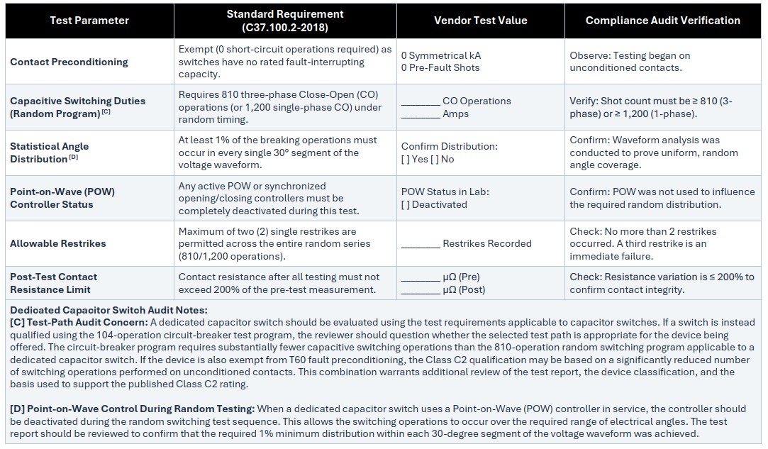
For a dedicated capacitor switch, the Class C2 designation should be evaluated together with the test sequence used to establish the rating. The following questions provide a practical means of determining whether the test program corresponds to the device classification and whether the reported results demonstrate the expected level of capacitive switching performance.
A. Test-Path Verification
1) Which Class C2 test sequence was used?
“The capacitor switch datasheet identifies the device as Class C2. Was this qualification established using the 810-operation random switching program, with point-on-wave control disabled, or using the 104-operation circuit-breaker test program?”
Audit Objective: Determine whether the dedicated capacitor switch was qualified using the random switching test sequence applicable to that device type or whether the circuit-breaker test path was used. If the circuit-breaker path was used, the preconditioning history should then be examined.
2) Was T60 short-circuit preconditioning performed?
“If the 104-operation circuit-breaker program was used to establish the Class C2 rating, did the test laboratory perform the three required T60 short-circuit breaking operations on the contacts before capacitive switching testing?”
Audit Objective: Determine whether the circuit-breaker test sequence was accompanied by the short-circuit preconditioning normally associated with that test path. If the device entered capacitive switching tests with unconditioned contacts, the reviewer should clearly understand the device classification, the exemption being applied, and the basis on which the resulting Class C2 rating is being presented.
3) Was worst-case minimum arcing time established?
“During capacitive switching type testing, was the normal Point-on-Wave (POW) target overridden or shifted to establish the worst-case minimum arcing time in accordance with the applicable test procedure? If so, what electrical offset was used?”
Audit Objective: Verify that the interrupting contacts themselves were demonstrated at the required worst-case switching condition rather than relying solely on the normal operation of the POW controller. This provides additional confidence in switching performance if the controller loses power, drifts, or otherwise fails to operate at its intended target.
Table 2. Dedicated Capacitor Switch Testing Sequence
VI. APPLICATION COMPLIANCE BEYOND TYPE TESTING
Successful type testing establishes the capability of the switching device under defined test conditions, but it does not by itself confirm that the device is properly applied in a particular capacitor bank or harmonic filter bank. The selected device must also be evaluated against the actual electrical duties imposed by the system.
These duties can include continuous current, capacitive switching current, back-to-back peak inrush current, inrush frequency, (I × f) capability, and mechanical outrush withstand. The applicable requirements also vary with device technology and classification, including vacuum and SF6 circuit breakers, dedicated capacitor switches, vacuum contactors, and legacy switching devices.
To simplify this evaluation, VarStec developed the Capacitor Bank Peak Inrush Analysis Tool, which consolidates the applicable calculation methods and evaluation criteria of IEEE Std C37.012-2022, IEEE Std C37.66-2021, IEEE Std C37.04-2018, and IEEE Std 1036-2020 into a single analysis environment. The tool supports multistage capacitor bank applications and automatically evaluates switching-device capability against the calculated system duty.
For additional application guidance, refer to VarStec Engineering Brief VEB-007, Medium-Voltage Capacitor Bank Switching: Peak Inrush Current and Device Rating Evaluation. This brief provides detailed guidance on calculating capacitor-bank inrush current, evaluating switching-device ratings, and addressing single-bank and back-to-back switching transients. It also provides additional background on the calculations and application checks incorporated into the VarStec Capacitor Bank Peak Inrush Analysis Tool, which is available in the Resource Hub at VarStec.com.
VII. CONCLUSION
A Class C2 or BC2 designation should not be evaluated independently of the test program used to establish it. Device classification, applicable standard, preconditioning requirements, test sequence, number of operations, and actual test results collectively determine what the published rating demonstrates.
A circuit breaker should first be qualified as a circuit breaker, and a dedicated capacitor switch should be qualified in accordance with the requirements applicable to capacitor switches. Additional testing can demonstrate enhanced capability, but it should supplement, not replace, the qualification appropriate to the device. Where differences between IEEE and IEC requirements are immaterial to the application, VarStec places greater emphasis on demonstrated switching performance and reliability than on the standards designation appearing on the nameplate.
For capacitor banks and harmonic filter banks, the final evaluation must also consider the actual system duty. The objectives are: identify the device, understand how it was tested, determine what those tests demonstrate, and verify that its capabilities are appropriate for the intended application. This provides a more meaningful basis for equipment selection than relying on a Class C2 or BC2 designation alone.
VIII. REFERENCES
[1] IEEE Std C37.100.2-2018, IEEE Standard for Common Requirements for Testing of AC Capacitive Current Switching Devices over 1000 V.
[2] IEEE Std C37.04-2018, IEEE Standard for Ratings and Requirements for AC High-Voltage Circuit Breakers with Rated Maximum Voltage Above 1000 V.
[3] IEEE Std C37.09-2018, IEEE Standard Test Procedures for AC High-Voltage Circuit Breakers with Rated Maximum Voltage Above 1000 V, Corrigendum 1-2021.
[4] IEEE Std C37.66-2021, IEEE Standard Requirements for Capacitor Switches for AC Systems (1 kV to 38 kV).
[5] IEEE Std C37.012-2022, IEEE Guide for the Application of Capacitive Current Switching for AC High-Voltage Circuit Breakers Above 1000 V.
[6] IEEE Std 1036-2020, IEEE Guide for the Application of Shunt Power Capacitors.
[7] IEC 62271-100:2021, High-Voltage Switchgear and Controlgear – Part 100: Alternating-Current Circuit-Breakers.
[8] IEEE Std C37.06-2009, IEEE Standard for AC High-Voltage Circuit Breakers Rated on a Symmetrical Current Basis – Preferred Ratings and Related Required Capabilities. [Withdrawn.]
[9] IEEE Std C37.09a-2005, IEEE Standard Test Procedure for AC High-Voltage Circuit Breakers Rated on a Symmetrical Current Basis – Amendment 1: Capacitance Current Switching. [Superseded.]
[10] IEEE Std 1247-2005, IEEE Standard for Interrupter Switches for Alternating Current, Rated Above 1000 Volts. [Superseded.]
IX. VITAE
Paul B. Steciuk
Paul B. Steciuk is Co-Founder and President of VarStec Power Solutions, Inc. He specializes in medium-voltage reactive compensation and power quality systems, including metal-enclosed capacitor banks and harmonic filter banks. He previously co-founded and served as President of Northeast Power Systems, Inc. He holds a B.S. in Electric Power Engineering from Rensselaer Polytechnic Institute and has authored more than 30 technical papers and articles on harmonic analysis, reactive compensation, and filter applications.
Peter A. Steciuk
Peter A. Steciuk is Co-Founder and Vice President of VarStec Power Solutions, Inc. with extensive experience in medium-voltage reactive compensation and power quality systems. He previously co-founded and served as Vice President of Engineering of Northeast Power Systems, Inc. His experience spans electrical, mechanical, structural, and thermal design of metal-enclosed capacitor banks, harmonic filters, and motor starting systems. He holds B.S. and M.S. degrees in Electric Power Engineering from Rensselaer Polytechnic Institute and a B.S. in Mechanical Engineering from the University at Buffalo.
- Abstract
- I. INTRODUCTION
- II. WHY IT MATTERS
- III. EVOLUTION OF IEEE CAPACITIVE SWITCHING STANDARDS
- IV. CIRCUIT-BREAKER CLASS C2 (BC2) AUDIT
- V. DEVICE CLASSIFICATION AND TEST-SEQUENCE VERIFICATION FOR DEDICATED CAPACITOR SWITCHES
- VI. APPLICATION COMPLIANCE BEYOND TYPE TESTING
- VII. CONCLUSION
- VIII. REFERENCES
- IX. VITAE