
Capacitor switching is one of the most demanding duties imposed on medium-voltage switches, contactors, and circuit breakers because it can produce high-frequency inrush and outrush currents, transient overvoltages, and significant transient recovery voltage (TRV). VarStec evaluates capacitor-switching applications using the applicable IEEE switchgear standards and application guidance, including IEEE C37.06-2009, the long-standing circuit-breaker rating standard now superseded by IEEE C37.04-2018; IEEE C37.09 for circuit-breaker testing; IEEE C37.011 for transient recovery voltage application; IEEE C37.012 for capacitive-current switching; IEEE C37.66-2021 for capacitor switches used on AC systems from 1 kV through 38 kV; and IEEE C37.100.2-2018 for common testing requirements applicable to AC capacitive-current switching devices above 1,000 V. For projects governed by IEC, European, or Canadian requirements, VarStec also considers the corresponding IEC 62271-series and applicable national standards, including areas where IEEE and IEC switchgear requirements have been progressively harmonized. This chapter addresses practical questions involving back-to-back capacitor switching, inrush-current-limiting reactors, capacitor-bank outrush, close-in fault duty, switching-device capability, legacy circuit breakers, transient recovery voltage, and the application of IEEE, IEC, and Canadian switchgear standards.
Capacitor Switching and Transients Technical Q&A
How do back-to-back switching events influence the requirement for inrush current limiting reactors?
When a capacitor stage is energized while adjacent stages are already in service, a “back-to-back” switching event occurs. The energized stages act as a low-impedance source, discharging accumulated energy into the incoming stage at extremely high frequencies, often exceeding several thousand Hertz. Without mitigation, this peak inrush current can exceed the “making” and “latching” capacities of the switching device, leading to contact welding or catastrophic failure.
VarStec utilizes the Capacitor Bank Peak Inrush Analysis Tool to calculate the peak magnitude and frequency of these transients. By quantifying the Ipeak and finrush, we determine the inductance required for current-limiting reactors to reduce the transient to within the applicable switching-device capability. For circuit breakers, the resulting duty is evaluated against the applicable ratings and test requirements of IEEE C37.04, IEEE C37.09, and IEEE C37.012; for dedicated capacitor switches, IEEE C37.66 and IEEE C37.100.2 are applied as appropriate.
Outrush current is the high-frequency, high-magnitude discharge of a capacitor bank into a low-impedance fault. As addressed in IEEE C37.012 and further detailed in IEEE PES-TR16, a critical duty can occur when a feeder or bus-tie circuit breaker located between the capacitor bank and the fault—sometimes referred to by VarStec as the “victim breaker”—closes into a pre-existing close-in fault.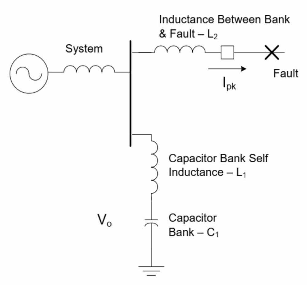
In this scenario, the victim breaker must withstand the combined stresses of the power system’s short-circuit current and the high-frequency capacitor-bank outrush current. The VarStec Capacitor Bank Outrush & Close-in Fault Analysis Tool calculates the peak outrush magnitude (Ipeak) and frequency (fo) so that the resulting duty can be compared with the breaker’s applicable high-frequency current and making or close-and-latch capability. Failure to properly limit this duty can result in contact welding or severe mechanical damage to the breaker. When applicable limits are exceeded, the VarStec analysis tool calculates the inductance required to reduce the outrush duty to within the breaker’s applicable capability.
While reactors are essential for limiting inrush and outrush, they introduce a secondary challenge: they can significantly increase the Transient Recovery Voltage (TRV) seen by a circuit breaker during fault interruption. When a breaker opens to clear a fault, the stored energy in the reactor produces a high-frequency voltage oscillation across the breaker contacts. If the rate of rise of this recovery voltage (RRRV) exceeds the dielectric strength of the opening gap, the arc may reignite, causing a failure to interrupt.
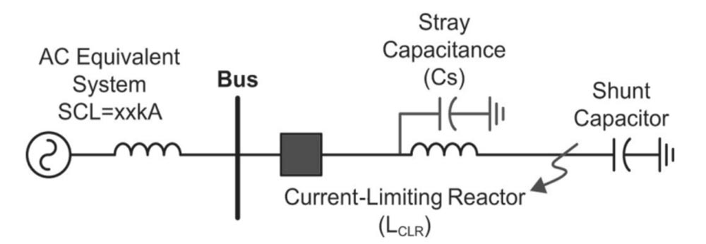
VarStec addresses this using the Reactor Limited Fault TRV & Breaker Duty Assessment Tool. This tool analyzes the interaction between the reactor’s inductance and the system’s stray capacitance to predict the TRV profile. By comparing the calculated TRV duty with the applicable circuit-breaker TRV ratings established by IEEE C37.04 and the application guidance of IEEE C37.011, we determine whether the selected breaker has adequate interrupting capability or whether additional TRV mitigation is required. Where necessary, mitigation may include properly applied TRV-delay or surge capacitors, or other engineered measures to reduce the rate of rise of recovery voltage.
The integration of a new capacitor bank into an existing substation with legacy oil circuit breakers (OCBs) requires transient analysis because these breakers may have limited high-frequency current and TRV capability relative to the duties created by the new capacitor bank. Many legacy OCBs were designed and tested under earlier breaker standards, before today’s breaker-rating, capacitive-switching, and TRV application framework, including IEEE C37.04, IEEE C37.011, and IEEE C37.012, and before later industry guidance such as IEEE PES-TR16 documented these application concerns in detail.
When a legacy OCB, or as VarStec calls it, a “victim breaker,” is exposed to a close-in fault, it can be subjected to high-frequency, high-magnitude outrush currents that exceed the mechanical and thermal limits of the oil-interruption mechanism. In addition, the presence of the capacitor bank alters the Transient Recovery Voltage (TRV) profile during fault interruption. Using the VarStec Reactor Limited Fault TRV & Breaker Duty Assessment Tool, we analyze the increased rate-of-rise of recovery voltage (RRRV) to help verify that the legacy equipment can successfully clear the fault without arc re-ignition.
Related Technical Topics
How VarStec Addresses Capacitor Switching Transients
VarStec designs medium-voltage capacitor banks and harmonic filter banks with full consideration of capacitor-switching duty and the transient stresses imposed on both the electrical system and the switching equipment. Applicable IEEE, IEC, and Canadian standards are used not only as design references, but also as part of VarStec’s evaluation of vendor-supplied circuit breakers, capacitor switches, contactors, and other switching devices before they are applied in our equipment. We review device ratings, capacitor-switching capability, relevant test requirements and available test documentation, and the relationship between the tested duty and the actual inrush, outrush, close-in fault, and transient recovery voltage (TRV) stresses expected in the application. A switching device that is improperly selected or applied can become a critical limitation on capacitor-bank and harmonic filter bank reliability, switching performance, and equipment life. By evaluating both the electrical system and the demonstrated capability of the switching device, VarStec develops System-Fit™ capacitor-bank and harmonic-filter-bank solutions engineered for reliable field performance.