Medium-voltage harmonic filter design involves much more than adding kvar or selecting a tuning frequency. Passive harmonic filters may be applied to absorb characteristic harmonic currents, reduce voltage and current distortion, damp or avoid system resonance, improve power factor, and help a facility meet applicable harmonic-performance requirements. Proper design requires evaluation of the electrical system, harmonic-current sources, system impedance, resonance conditions, filter topology, tuning frequency, Q-factor, capacitor and reactor duty, component tolerances, and expected operating configurations. Guided by IEEE 519, IEEE 18, IEEE 1531, and more than 30 years of practical harmonic-filter experience, VarStec develops System-Fit™ harmonic filter solutions engineered for the electrical system and operating duty of each application. This Technical Q&A addresses practical questions about notch, high-pass, C-high-pass, and H-Type harmonic filters, filter tuning, resonance damping, component ratings, capacitor-bank configuration, altitude derating, and harmonic filter design margins.
Medium-Voltage Harmonic Filter Design Technical Q&A
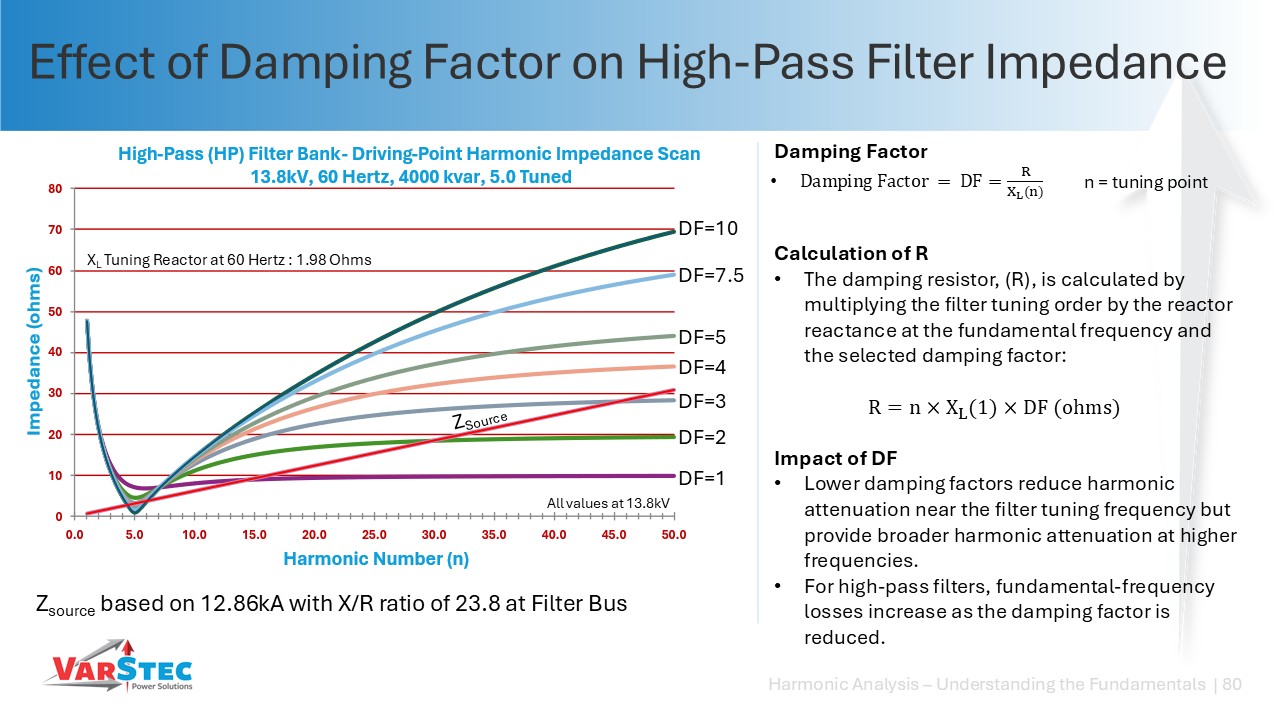
To understand the significance of the Q-factor (or damping factor, DF) in the design of a damped high-pass filter, one must evaluate how this parameter dictates the shape of the filter’s impedance curve and its corresponding physical power losses.
- Curve Control: The Q-factor (modeled as the ratio of parallel resistance to the reactor’s reactance at the tuning frequency, R/XL) determines the “sharpness” of the filter’s notch. A high Q-factor (high parallel resistance) results in a highly-tuned, sharp notch that behaves almost identically to a standard notch filter, offering very low impedance and highly effective filtering near its tuning frequency.
- Broadband Attenuation: As the Q-factor is decreased (lower parallel resistance), the filter becomes more “damped”. This flattens and broadens the impedance curve, meaning the filter becomes less effective at its specific tuning frequency but more effective at attenuating a wide range of higher-order frequencies and smoothing out parallel resonances from stray capacitance or nearby capacitor banks.
- Fundamental Losses: The trade-off of a lower Q-factor is that a lower parallel resistance forces more fundamental frequency current (50/60 Hz) to flow through the resistor, increasing continuous I2R fundamental losses.
The figure below, taken from VarStec’s Power Session Series shows a 5th tuned high-pass filter and how it’s driving point impedance changes with its damping factor.
VarStec’s Perspective
VarStec recommends starting the high-pass filter design process with a high Q-factor (high parallel resistance) to minimize fundamental operating losses and restrict resistor physical sizes. Engineers should only decrease the Q-factor (increase damping) iteratively when modeling shows that it is necessary for performance. When losses become too high, consideration should be given to using the C-High-Pass Harmonic filter as this type of filter has an equivalent driving point impedance profile, but has near zero losses at the fundamental.
Tuning a harmonic filter slightly below its target harmonic, for example, tuning a 5th-harmonic filter to approximately the 4.7th harmonic (282 Hz on a 60 Hz system), is a common design practice used to control resonance, accommodate component tolerances and aging, and limit excessive harmonic-current absorption.
Four primary considerations drive this practice:
1. Keep Parallel Resonance Away from Dominant Harmonics
When a series-tuned LC filter is connected to an inductive power system, the filter and source impedance create a parallel resonance, or anti-resonance, below the filter’s series-tuning frequency.
- If a filter is tuned exactly to the 5th harmonic, the associated parallel-resonance peak may fall relatively close to the 5th harmonic.
- Changes in filter capacitance can shift both the series and parallel-resonant frequencies. In particular, loss of capacitance shifts the tuning frequency upward. It should be noted that medium-voltage capacitors do not lose capacitance over time. They fail, but do not lose capacitance over time. Low voltage capacitors on the other hand, typially use self-healing metallized polypropylene dielectric construction. During normal operation, localized dielectric breakdowns are cleared through the self-healing process, which vaporizes a small area of metallization around the fault. Over time, the cumulative effect of these self-healing events gradually reduce the capacitor’s effective capacitance.
- If the parallel-resonance peak moves onto a dominant harmonic, such as the 5th, harmonic currents can be amplified rather than suppressed, producing excessive voltage distortion and potentially damaging overvoltages.
- Tuning below the target harmonic moves the parallel-resonance peak farther below the dominant harmonic, reducing the likelihood that normal component or system variations will shift it into a hazardous region.
2. Allow for Capacitor Aging and Detuning
Filter capacitance can decrease over time because of capacitor aging, element clearing, or fuse operation. Since resonant frequency varies inversely with the square root of capacitance, a reduction in capacitance causes the filter tuning frequency to increase. This is a low voltage concern.
Designing the filter below the target harmonic therefore provides upward tuning margin. Rather than allowing normal capacitance loss to push an initially sharp-tuned filter above the target harmonic, the filter can gradually drift toward it while remaining within an acceptable operating range.
3. Accommodate Manufacturing Tolerances
Reactors and capacitors both have manufacturing tolerances that affect the filter’s actual tuning frequency. The combined tolerance of the installed components can produce a tuning point different from the calculated nominal tuning pont.
Designing with sufficient margin below the target harmonic helps prevent normal component tolerances from inadvertently producing an over-tuned filter or placing a resonance too close to a dominant system harmonic.
4. Limit Background Harmonic-Current Absorption
A filter tuned very close to a dominant harmonic presents very low impedance at that frequency. While this improves filtering, it can also cause the filter to absorb harmonic current originating elsewhere on the power system, not just harmonic current produced by the load it was designed to serve.
Excessive background harmonic-current absorption can overload the filter reactor and capacitors and may require higher equipment ratings.
Tuning slightly below the target harmonic increases the filter impedance at the exact harmonic frequency, providing effective local harmonic mitigation while reducing exposure to excessive grid-side harmonic current.
VarStec Perspective
The traditional practice of tuning a 5th-harmonic filter near the 4.7th harmonic is a useful starting point, but it should not be applied as a universal rule. The proper tuning frequency depends on the system characteristics, harmonic spectrum, filter configuration, component tolerances, operating conditions, and performance requirements of the harmonic filter.
VarStec evaluates the driving-point impedance and frequency-response characteristics of the complete system before establishing final tuning frequencies. This is particularly important in multi-stage harmonic filters, where independently selecting conventional tuning points, such as 4.7th, 6.7th, and 10.7th, for example, can create undesirable inter-harmonic resonances or circulating currents between filter branches.
Depending on the system, the optimum design may require tuning right on a dominant harmonic, such as 5.0 or in some applications, slightly above it. These decisions are base on detailed harmonic and impedance analysis rather than a fixed tuning rule.
A high-pass or C-high-pass filter should be considered when the system has interharmonics or when parallel capacitance creates resonance conditions that need to be damped.
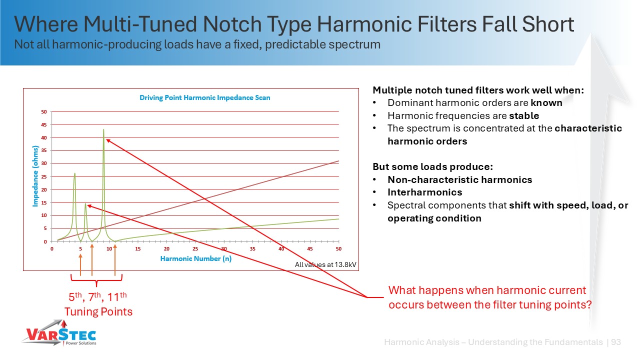
- Interharmonics can interact with notch-filter resonances: A notch filter creates a parallel resonance, commonly called an anti-resonance, below its tuning frequency. In a multi-tuned notch-filter system, additional anti-resonant points are created between each filter tuning frequencies. If the load produces interharmonics, those interharmonic frequencies can line up with one of these resonances and cause high voltage distortion and poor filter performance. This can occur with loads such as cycloconverters and AC arc furnaces, where the harmonic frequencies can change with operating conditions.
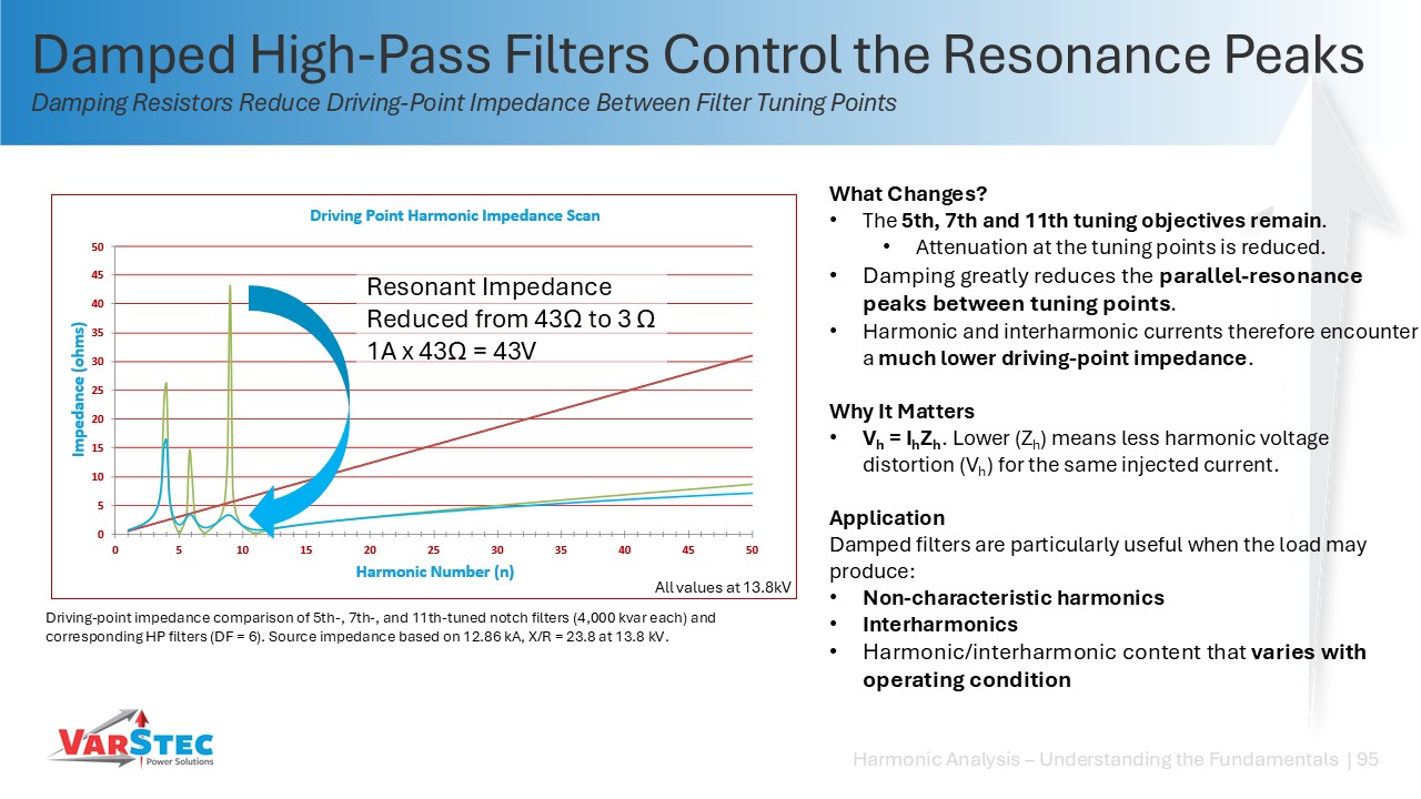
- High-pass filters damp these resonances: A high-pass or C-high-pass filter adds damping to the anti-resonant points created by the filter system. In a multi-tuned harmonic filter system, this reduces the resonant peaks between the individual tuning points and makes the system much less sensitive to interharmonics. The impedance scans below, presented in VarStec’s Power Sessions, show why multi-tuned notch filters can create problems in systems with interharmonics and how high-pass filters can be used to control those resonances.
- High-pass filters can also damp resonance caused by other capacitance: Parallel resonance can also be created by nearby shunt capacitor banks or cable capacitance. In these cases, a high-pass or C-high-pass filter can be used to damp the resonance. This can also provide an economical design option: one damped filter may be used to control the system resonance while the remaining reactive power is supplied by lower-cost conventional shunt capacitor banks.
VarStec Perspective
Notch filters work well when the harmonics are known, predictable, and occur at characteristic harmonic frequencies. When the load produces interharmonics or harmonic frequencies that change with operating conditions, VarStec generally favors a high-pass or C-high-pass filter because it damps the resonances that could otherwise interact with those frequencies.
High-pass and C-high-pass filters are also useful when shunt capacitor banks or cable capacitance create an unacceptable parallel resonance. In some applications, a single damped filter can control that resonance while allowing the balance of the required kvar to be supplied with conventional shunt capacitor banks.
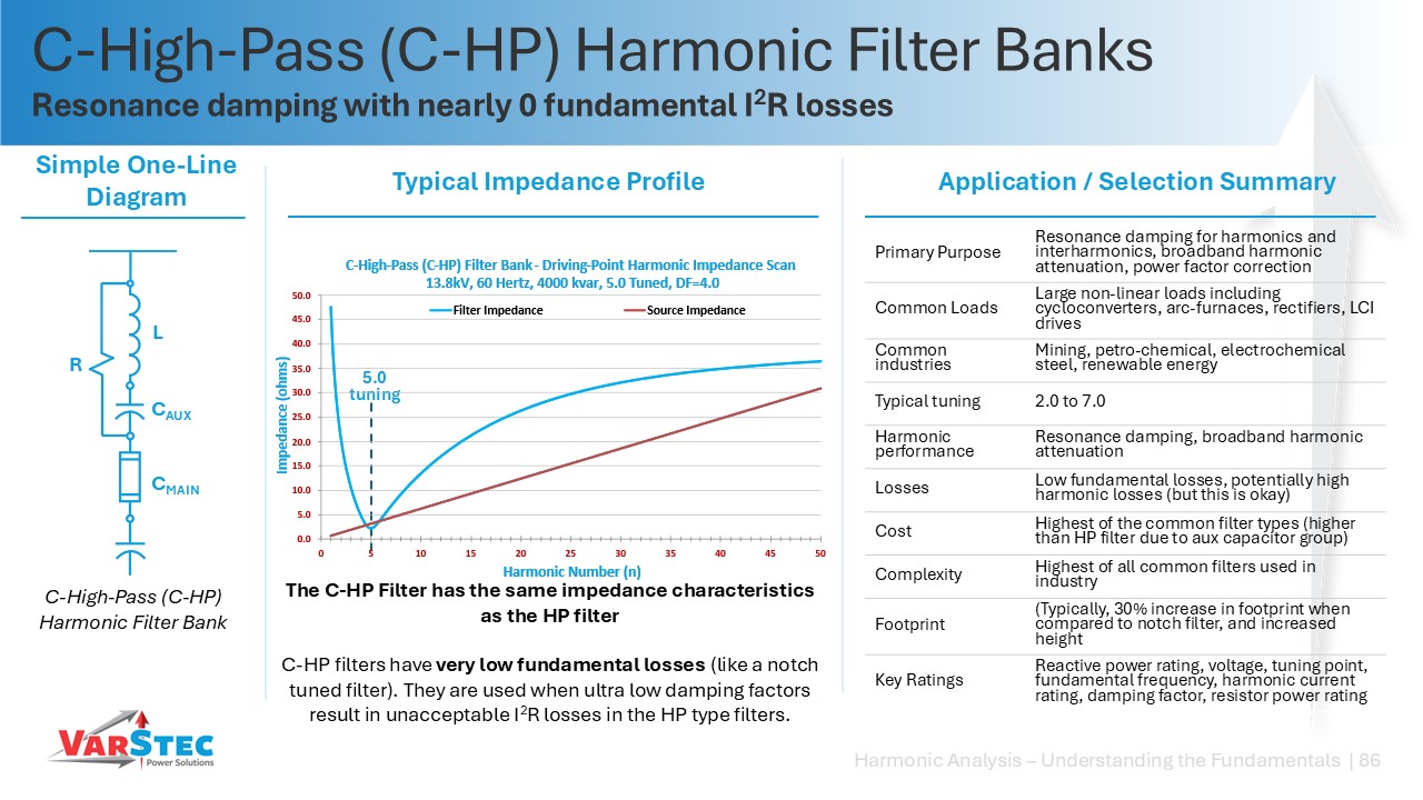
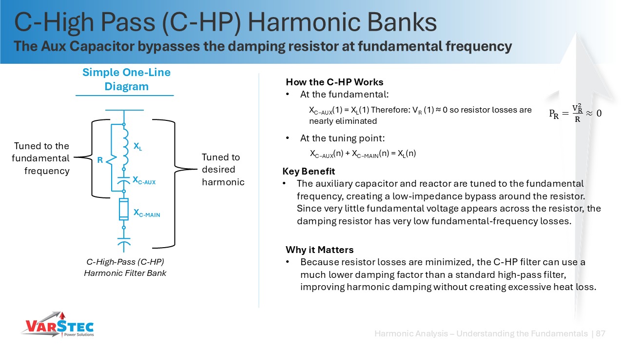
A C-high-pass filter incorporates an auxiliary capacitor (CAUX) tuned with the reactor (L) to the fundamental frequency 50Hz/60Hz.
- Efficiency: This tuning effectively bypasses the damping resistor at the fundamental frequency, resulting in negligible fundamental-frequency power losses.
- Performance: It allows for aggressive damping (very low Q-factors) without the kW losses with standard high-pass resistors.
The two presenentation slides extracted from VarStec’s Power Sessions cleary show the theory of operation of a C-high-pass (C-HP) harmonic filter operates.
Per IEEE Std 18-2025, IEEE Standard for Shunt Power Capacitors, shunt power capacitors are intended to operate normally at or below their rated voltage. Under contingency system or capacitor-bank conditions, however, they are designed for continuous operation provided that none of the following limits are exceeded:
- 110% of rated RMS voltage
- 120% of rated peak voltage, including harmonics but excluding transients
- 135% of nominal RMS current, based on rated kVAR and rated voltage
- 135% of rated kVAR
These values are maximum continuous capability limits and should not be treated as normal design targets. This distinction becomes particularly important in harmonic filter applications because the capacitor is exposed to voltage and current stresses from both the fundamental frequency and the harmonic spectrum.
RMS Voltage
For a harmonic filter, capacitor RMS voltage cannot be evaluated using system fundamental voltage alone. The capacitor sees the fundamental-frequency system voltage plus the additional fundamental-frequency voltage developed across the capacitor as a result of the series reactor. The design must therefore begin with the maximum expected system operating voltage. VarStec evaluates the filter at a conservative 110% system-voltage condition. The resulting capacitor fundamental voltage must then be combined with voltage rise caused by the tuning reactor and also the individual harmonics voltages that result from the harmonic current flow through the capacitor’s capacitive reactance (Xc). It is the route sum squared of all of these values that determine the actual RMS voltage stress on the capacitor. This total RMS capacitor voltage must remain within the allowable capacitor operating limit.
Peak Voltage
Peak voltage requires a separate evaluation because a capacitor can satisfy its RMS-voltage limit while exceeding its allowable dielectric peak stress. The capacitor waveform consists of the fundamental voltage plus each harmonic voltage. The peak value of the resulting waveform must remain below the IEEE 18 limit of 120% of rated peak voltage.
For conservative equipment sizing, VarStec evaluates the maximum system fundamental voltage, reactor-induced fundamental voltage rise, and harmonic-voltage components assuming that their peaks combine in the most unfavorable manner. A conservative upper-bound check can therefore be made by assuming coincident harmonic peaks rather than relying on favorable harmonic phase relationships. This approach provides additional dielectric margin because the design does not depend upon harmonic phase angles remaining favorable throughout the life of the installation.
RMS Current
Capacitor current must similarly include both fundamental and harmonic currents. The fundamental current should be calculated at the maximum system operating voltage, including the effect of the filter reactor, and then combined with all significant harmonic currents. The resulting value must remain below the IEEE 18 maximum continuous contingency capability of 135% of nominal RMS current.
Capacitor kVAR Loading
Capacitor reactive-power loading must also be evaluated using the actual voltage and harmonic environment rather than simply comparing the filter’s nominal fundamental-frequency kVAR with the capacitor nameplate. At fundamental frequency, capacitor kVAR increases approximately with the square of capacitor voltage. The additional capacitor voltage produced by the series reactor therefore increases capacitor loading even before harmonic contributions are considered. Harmonic voltages and currents create additional reactive loading that must also be included when evaluating the capacitor against the IEEE 18 limit of 135% of rated kVAR.
VarStec Practical Application Note
VarStec does not design harmonic-filter capacitors to routinely operate near the IEEE 18 contingency limits. These limits are treated as maximum equipment capabilities, not as available design margin that should be consumed during normal operation.
For harmonic filter design, VarStec evaluates capacitor duty using a conservative maximum-voltage condition and accounts for:
- Maximum expected system fundamental voltage
- Fundamental-frequency capacitor voltage rise produced by the filter reactor
- Individual harmonic voltages
- Total RMS capacitor voltage
- Worst-case capacitor peak voltage, including harmonic components
- Fundamental and harmonic currents
- Total capacitor RMS current
- Fundamental and harmonic reactive-power loading
The capacitor voltage and kVAR ratings are then selected with sufficient margin so that reasonable changes in system voltage, harmonic loading, system impedance, or operating configuration do not place the capacitor near its maximum allowable limits. This is an intentional VarStec design philosophy. A harmonic filter consists of a relatively small number of major power components, the capacitors, reactors, damping resistors, and switchign devices. Increasing capacitor voltage, current, or kVAR capability typically represents a relatively small incremental cost compared with the total cost of the harmonic filter bank. VarStec therefore prefers to invest in additional capacitor capability and design margin rather than use the IEEE 18 contingency limits as normal operating limits. The objective is to make capacitor electrical and thermal stress a non-issue over the expected operating range of the filter and throughout its service life.
To learn more about harmonic filter design, see VarStec’s Engineering Brief, Medium-Voltage Harmonic Filter Design: Engineering for Reliability. There you will find VarStec’s Filter Desgin spreadsheet tool that provides reliable harmonic filter design for notch tuned, high-pass (HP), C-high-pass (C-HP), and H-Type harmonic filters.
The VarStec harmonic filter design spreadsheet requires inputs including the system voltage and frequency, reactive power requirements, current injection data, the desired tuning point, and the damping factor.
The capacitor voltage rating must be higher because it is subjected to two primary additive stresses:
- Fundamental Rise: The series tuning reactor creates a fundamental-frequency voltage rise on the capacitor.
- Harmonic Stress: Harmonic currents flowing through the capacitor produce additional harmonic voltage.
VarStec Engineering Note: Per IEEE 18, the 110% RMS and 120% peak voltage margins are for contingency operations and should not be used in the normal operating range of the harmonic filter.
Both iron-core and air-core reactors can provide equivalent harmonic-filter performance when properly designed and applied. The primary differences are their magnetic behavior, physical size, stray magnetic fields, losses, and installation requirements.
- Iron-Core Reactors: Use a gapped magnetic core to establish the required inductance. Because the high-permeability core confines nearlly all of the magnetic flux, an iron-core reactor requires relatively few winding turns and can be made considerably more compact than an equivalent air-core reactor. The low external magnetic field makes iron-core reactors particularly well suited for metal-enclosed harmonic filter banks, where reactors, capacitors, switching devices, and protection equipment must be installed within a relatively compact enclosure.
The primary design concern is magnetic saturation. Reactor RMS current rating alone is therefore not sufficient. The winding must be thermally designed for the fundamental and harmonic RMS currents, while the magnetic core must have adequate flux capability for the maximum instantaneous current produced by the combined fundamental and harmonic currents. VarStec requires substantial design margin so that the reactor remains sufficiently linear during worst-case harmonic conditions rather than allowing its inductance to collapse as the core approaches saturation.
- Air-Core Reactors: Contain no magnetic iron core and therefore do not experience magnetic-core saturation. Their inductance is established primarily by the geometry and number of turns of the winding. However, because there is no magnetic core to contain the flux, substantial magnetic fields extend outside the reactor.
These stray fields can induce eddy-current heating in nearby steel, reinforcing bar, ground grids, structural members, enclosures, and other conductive loops. Nearby conductive structures can also affect the reactor’s inductance. Consequently, air-core reactors generally require substantially greater physical clearance, special structural arrangements, or magnetic shielding and are therefore more commonly applied in open-air harmonic filter installations rather than compact metal-enclosed systems.
- Physical and Economic Considerations: For the same inductance and current rating, iron-core reactors generally have fewer winding turns, lower stray magnetic fields, smaller space requirements, and are easier to integrate into an enclosure. Air-core reactors eliminate saturation concerns but require greater installation space and more careful consideration of foundations, structural steel, enclosure design, and surrounding conductive materials.
VarStec Standard:
VarStec specifies iron-core filter reactors with a fundamental-current rating of at least 1.5× the calculated fundamental current and a harmonic-current rating of at least 2.0× the calculated harmonic RMS current, or 0.5× the filter fundamental-current rating, whichever is greater. The 1.5× fundamental-current margin means that, under the expected fundamental-current duty, winding losses are approximately 44% of the reactor’s corresponding thermal-loss capability, providing substantial thermal margin. In addition to these RMS thermal ratings, the reactor core must be designed with sufficient flux margin to avoid saturation under the maximum combined fundamental and harmonic current waveform.
An ungrounded split-wye capacitor bank connection is preferred because it eliminates 0-sequence resonance concerns, prevents false trips from neutral-to-ground voltage shifts during external line-to-ground faults, and it prevents high recovery voltages from causing restrikes in switching devices.
The Reverse Calculator Tools are used when the physical filter components are already known, such as the reactor inductance, capacitor capacitance or kvar rating, and, for damped filters, the resistor value, but the original filter design parameters are unknown. This commonly occurs when evaluating existing installations, legacy filters with incomplete documentation, or customer/EPC-supplied component selections.
Rather than designing the filter forward from a specified kvar rating, tuning point, and damping factor, the reverse calculator works backward from the known component values to determine the filter’s resulting:
- Effective reactive power rating
- Tuning frequency or harmonic tuning point
- Damping factor, where applicable
The VarStec Design Spread Sheet Tool includes reverse calculators for Notch, High-Pass (HP), and C-High-Pass (C-HP) filters.
Once these parameters have been determined, they can be entered into the corresponding VarStec forward-design worksheet. The complete filter can then be evaluated for capacitor voltage and current duty, reactor loading, resistor loading and losses, harmonic performance, and other component-rating requirements. This makes the reverse calculators particularly useful for reverse-engineering and validating an existing or externally supplied harmonic filter design, rather than simply determining what component values were originally intended.
While altitudes above 1,000 meters (3,300 feet) reduce air density and traditionally dictate applying an Altitude Correction Factor to increase equipment BIL, upsizing the filter bank BIL rating is not strictly required if surge arresters are utilized.
- IEEE Standards (IEEE C37.010, C37.20.2, and C37.20.3): These standards explicitly state that derating dielectric capabilities is usually not the most economical approach, and that applying properly coordinated surge arresters to keep transient voltages below the altitude-reduced insulation levels should be considered instead.
- IEC Standards (IEC TR 62271-306 and IEC 60694): These standards validate the same mitigation strategy, noting that the application of surge arresters to lower the required insulation level of the substation may result in a more advantageous choice of equipment.
VarStec Engineering Tip: The VarStec Capacitor Bank Altitude Derating & Insulation Coordination Tool as explained in VarStec’s VEB-005 Engineering Brief – Medium-Voltage Altitude Derating & Insulation Coordination Brief, follows the methodologies of IEEE C62.22 and IEC 60071-2 to mathematically evaluate both approaches. It helps verify equipment ratings and determine whether standard sea-level equipment can be safely applied at high elevations without unnecessarily increasing the BIL rating.
Under IEEE Std 18-2025, power capacitors rated over 600 V are provided with internal discharge devices that reduce the residual capacitor voltage to 50 V or less within 5 minutes after disconnection from the peak of rated voltage. Other standards specify somewhat different discharge criteria. IEC 60871-1:2014, applicable to shunt capacitors above 1,000 V and including capacitors used in harmonic filters, requires the residual voltage to be reduced to 75 V or less within 10 minutes. In Canada, CSA C22.1, Canadian Electrical Code, Rule 26-222, requires capacitors rated above 750 V to be discharged to 50 V or less within 5 minutes, effectively aligning the medium-voltage discharge requirement with IEEE 18. CSA C22.2 No. 190:14 (R2024) is the corresponding Canadian product standard for power-factor-correction capacitors and capacitor assemblies through 46 kV.
VarStec Perspective:
The discharge time is important not only for personnel safety but also for capacitor-bank switching. Under conventional IEEE-based designs, VarStec normally applies a 5-minute re-energization inhibit after a capacitor bank or harmonic filter bank stage has been de-energized. This prevents the system voltage from being reapplied while a significant trapped charge remains on the capacitors. IEEE 1531 specifically identifies this five-minute opening-to-closing delay as normal practice for filters using IEEE 18 capacitor units.
Where the application requires faster cycling, VarStec can provide several alternatives:
- Reduced-discharge-time capacitors: Capacitors can be specified with lower-value internal discharge resistance to reduce the discharge period, typically to approximately 3 minutes where available. The tradeoff is increased continuous resistor losses, which limits how far the internal discharge time can practically be reduced.
- Charged-bank switching: For applications requiring very fast reactive-power response, VarStec uses ABB’s VD4-CS1 capacitor-switching breaker. Its controlled-switching system allows the breaker to close onto a capacitor bank without waiting for the bank to discharge. ABB specifies a minimum interval of approximately 200 ms between operations in its fastest duty cycle. VarStec applies this capability in their hybrid STATCOM systems, where capacitor stages may need to become available again almost immediately to support voltage regulation and system stability.
- Fast-discharge coils: In applications such as VarStec MotorVar™ capacitive motor-starting systems, an external fast-discharge coil can be applied to each stage. The capacitor stage can be discharged in approximately 2 seconds, with the control system verifying the discharge and permitting the stage to be re-energized in approximately 10 seconds. This allows one MotorVar system to sequentially start multiple motors without waiting five minutes between starts.
Regardless of the internal discharge device or switching method, a capacitor’s discharge resistor should never be considered a substitute for proper grounding and short-circuiting procedures before personnel work on the capacitor bank.
Under IEEE Std 18-2012, shunt power capacitor units are designed for continuous operation and frequent switching, indoors or outdoors, at a maximum average ambient temperature of 46°C (114.8°F) over a 24-hour period, with a maximum peak ambient temperature of 55°C (131°F). The ambient temperature is measured in the vicinity of the capacitor at a location where heat generated by the capacitor itself does not appreciably affect the measurement.
It is important to distinguish ambient temperature from capacitor case temperature or internal hot-spot temperature. The IEEE limit refers to the temperature of the surrounding air. IEEE defines ambient temperature as the temperature of the air into which the equipment dissipates its heat; for self-ventilated equipment, this is essentially the air in the immediate vicinity of the equipment.
For actual capacitor-bank applications, IEEE Std 1036-2020 provides more specific maximum ambient-temperature guidance based on the capacitor mounting arrangement:
- Isolated capacitor 46°C (115°F)
- Single row of capacitors 46°C (115°F)
- Multiple rows and tiers of capacitors 40°C (104°F)
- Metal-enclosed or housed equipment 40°C (104°F)
For Table 4 of IEEE 1036-2020, the listed maximum ambient temperature is defined as the arithmetic average of the four highest hourly temperature readings during the hottest day expected at the capacitor location. For applications above these temperatures, IEEE 1036 directs the user to consult the capacitor manufacturer. The guide states that these ratings apply to switched or continuously operated capacitors in outdoor locations with unrestricted ventilation and direct sunlight.
The lower 40°C application limit for multiple-row, multiple-tier, and metal-enclosed arrangements reflects the effect that the installation itself has on heat dissipation. IEEE 1036 explains that capacitor ratings depend on both radiation and convection. An isolated, non-enclosed capacitor dissipates heat most effectively—approximately 45% by radiation and 55% by convection. Placing capacitors side-by-side or in multiple tiers raises their operating temperature because the air becomes progressively warmer and radiative heat transfer is restricted.
Enclosures also require careful thermal design. IEEE 1036 specifically cautions that placing capacitors in a housing or room without forced-air ventilation increases temperature rise because radiation is reduced and natural air circulation is restricted. The same section also states that capacitors exposed to radiation from the sun or another surface above ambient temperature experience a higher temperature rise.
Temperature is particularly important for power capacitors because they commonly operate for long periods at full electrical loading and at comparatively high dielectric stress. IEEE 1036 therefore cautions that prolonged operation at elevated temperature can result in gradual dielectric deterioration and shortened capacitor life.
IEEE Std 18 also verifies thermal capability through a thermal-stability design test. During this test, the capacitor is installed between barrier capacitors at the manufacturer’s minimum recommended spacing and in the mounting position expected to produce the highest internal temperature. The air inside the test enclosure is maintained at an average of 46°C without forced circulation, while the test capacitor is electrically loaded to at least 144% of rated kvar.
Therefore, 55°C should not be interpreted as a normal continuous design ambient for a capacitor bank. Under IEEE 18-2012, 55°C is the allowable peak ambient, while 46°C is the maximum 24-hour average ambient for the capacitor unit. For actual bank installations, IEEE 1036-2020 further reduces the maximum expected ambient to 40°C for multiple-row/tier arrangements and metal-enclosed or housed equipment, unless the equipment is specifically engineered and approved for higher temperatures.
VarStec Perspective:
The standards establish ambient-temperature limits, but ambient air temperature is only part of the thermal problem. In hot, high-solar-radiation environments, the thermal design of the complete capacitor bank or harmonic filter bank must also account for solar heat gain, capacitor self-heating, equipment arrangement, ventilation, enclosure temperature rise, altitude, and the ability of the equipment to reject heat.
Solar loading can raise equipment surface temperatures significantly above the surrounding ambient air temperature, and exterior color has a major influence on how much solar energy is absorbed. Anyone who has placed a hand on a white vehicle and then on a darker gray vehicle after both have been sitting in the sun has experienced the difference firsthand, the darker surface becomes noticeably hotter. White and other high-reflectance finishes absorb less solar radiation and therefore help reduce enclosure surface temperature and the heat transferred to the equipment inside. This is one reason white is such a common vehicle and fleet color in hot, high-solar-radiation regions such as Texas, and the same basic thermal principle applies to capacitor-bank and harmonic-filter enclosures. The elevated surface temperature from the sun represents an additional radiative and conductive heat source that can increase capacitor operating temperature. IEEE 1036 independently confirms this effect by stating that solar radiation increases capacitor temperature rise.
This is particularly important in desert, mining, oil and gas, solar-generation, and other installations where summer ambient temperatures may reach 40°C to 50°C or higher. At these temperatures, very little thermal margin remains. IEEE 1036 specifically requires consultation with the capacitor manufacturer when expected ambient temperatures exceed the limits in its Table 4.
Metal-enclosed construction by itself does not make capacitors cooler. In fact, IEEE 1036 warns that an enclosure without adequate ventilation can increase temperature rise. The advantage of a properly engineered metal-enclosed system is that the enclosure gives the designer tools that are difficult to apply to an open-air capacitor bank:
- White or high-solar-reflectance exterior surfaces can reduce absorbed solar energy.
- Solar shielding and enclosure construction can prevent direct solar radiation from striking individual capacitor cases.
- Forced-air ventilation can move heat away from capacitor units and prevent stagnant hot-air pockets.
- Filtered ventilation or closed-loop cooling can provide cooling while limiting the entry of abrasive sand and dust.
- Proper capacitor spacing and airflow paths can prevent heat from one capacitor or row from preheating the cooling air entering another.
- Where necessary, air conditioning or other active cooling systems can maintain acceptable internal temperatures even when the external ambient exceeds normal capacitor-bank application limits.
This becomes still more important when high temperature is combined with high altitude, where reduced air density decreases convective cooling effectiveness. IEEE Std 18-2012 identifies operation above 1800 m (6000 ft), inadequate ventilation, excessive abrasive or conductive dust, and operation outside its normal ambient-temperature range as abnormal service conditions that may require special equipment construction.
For this reason, VarStec evaluates the thermal environment of the complete capacitor bank or harmonic filter bank, rather than simply checking the nameplate temperature capability of the individual capacitor unit. For hot and sunny installations, the practical design philosophy is straightforward:
Think White. Think Shade. Think Cooling. Think Metal-Enclosed.
The objective is not merely to select a capacitor capable of surviving a stated outdoor ambient temperature. It is to design the complete system so that solar loading, internal electrical losses, capacitor arrangement, enclosure heat gain, ventilation, altitude, dust, and the site’s actual temperature profile are all considered together, allowing the capacitor units to operate within their intended thermal limits and achieve reliable service life.
A design margin is recommended because harmonic filters are expected to operate for 20+ years, while the electrical system around them will change. The harmonic currents calculated during the original study should therefore not be treated as exact or permanent.
Design margin helps account for:
- Future load growth: New drives, rectifiers, and other nonlinear loads can add harmonic current. Because the filter presents a low-impedance path near its tuning frequency, these currents can be drawn into the filter.
- Changes in the utility system: Source impedance changes as utility transformers, feeders, generation, and neighboring industrial loads change, which can increase the harmonic-current flow through the filter.
- Ambient voltage distortion: Ambient harmonic voltage distortion from the source can drive additional harmonic current into the filter. This distortion is often not well known during design and can change over time.
- Modeling uncertainty: Utility data, source impedance, transformer and cable parameters, load harmonic spectra, and operating configurations are never known with perfect accuracy.
- Unaccounted-for capacitance: Cables, capacitor banks, and future power-factor-correction equipment can shift resonant frequencies and increase harmonic amplification.
- Internal harmonic amplification: In multi-stage filter systems, anti-resonances between tuning points can amplify harmonic current above the levels predicted from the nonlinear loads alone.
- Reactor saturation: Iron-core reactors can saturate if harmonic current exceeds the design level, resulting in increased current, heating, noise, and potentially rapid failure.
- Thermal stress: Reactor and resistor losses are proportional to approximately I²R. Operating at 50% of rated current produces only about 25% of the I²R heating associated with rated current, providing substantial thermal and reliability margin.
- Capacitor overstress: Higher-than-expected harmonic current increases capacitor RMS current, RMS voltage, and peak voltage, potentially reducing capacitor life or exceeding its operating limits.
VarStec Perspective
VarStec designs harmonic filter banks for long-term reliability, not merely to pass the harmonic study performed at the time of purchase. The objective is to provide equipment capable of operating for 20+ years with essentially zero component failures, recognizing that the electrical system surrounding the filter will almost certainly change during that period.
Where practical, VarStec prefers substantial harmonic-current margin and will often select reactors and resistors with current capability approaching twice the calculated normal operating duty. Operating a component well below its thermal capability dramatically reduces I²R heating while providing reserve capacity for future loads, background distortion, modeling uncertainty, harmonic amplification, and changes in system impedance. Capacitors are similarly selected and verified with adequate margin against their applicable RMS-current, RMS-voltage, peak-voltage, and reactive-power limits.
The economics strongly favor this approach. Increasing the harmonic current capability of the reactors, capacitors, and resistors typically represents only a small fraction of the total installed cost of a medium-voltage harmonic filter bank. That incremental cost is minor compared with the cost of replacing a failed component, mobilizing personnel, troubleshooting the system, shutting down a process, and absorbing the production losses associated with an unexpected outage.
Related Technical Topics
30+ Years of Harmonic Filter Design Experience
VarStec brings more than 30 years of practical experience in the design, application, and manufacturing of complex harmonic filter systems. Our expertise spans large rectifier systems in chemical processing, mining VFDs, and LNG facility drives. Building on that experience, VarStec has developed a harmonic filter design spreadsheet tool to help engineers properly design and rate the components against IEEE 18 and IEEE 1531 to ensure your system performs as modeled for the life of the plant.