
Power factor fundamentals are essential to understanding how real power, reactive power, apparent power, and harmonic distortion affect industrial and medium-voltage power systems. This Technical Q&A answers common questions about kW, kVAR, kVA, displacement power factor, true power factor, and the practical application of medium-voltage power factor correction equipment.
Power Factor Fundamentals Technical Q&A
kW (kilowatts) represents real power, the portion of electrical power that performs useful work, such as driving a motor shaft, producing heat or light, and operating process equipment.
kVAR (kilovolt-amperes reactive) represents reactive power, the portion of electrical power associated with establishing and sustaining the magnetic and electric fields required by AC equipment. Reactive power does not directly produce useful mechanical or thermal work, but it is essential to the operation of many electrical loads, particularly motors and transformers.
kVA (kilovolt-amperes) represents apparent power, the vector combination of real power (kW) and reactive power (kVAR). It represents the total electrical loading imposed on generators, transformers, cables, switchgear, and other power-system equipment.
In practical terms, a facility may require both kW and kVAR from the electrical system. As reactive power demand increases, the kVA and current required to deliver the same amount of useful kW also increase. This results in greater electrical losses, reduced available system capacity, increased voltage drop, and, in some cases, utility power-factor penalties or demand charges.
These three quantities are commonly illustrated using the power triangle, where kW is shown along the horizontal axis, kVAR along the vertical axis, and kVA as the hypotenuse. The angle between kW and kVA is the power-factor angle, commonly designated as Ø.
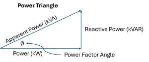
By conventional load notation, inductive loads consume reactive power and are represented by positive kVAR, while capacitive equipment supplies reactive power and is represented by negative kVAR. Accordingly, inductive kVAR is commonly plotted above the horizontal axis and capacitive kVAR below it.
Inductive equipment such as induction motors, transformers, and reactors typically consumes reactive power. Equipment used to supply or control reactive power includes capacitor banks, harmonic filter banks, overexcited synchronous motors and synchronous condensers, generators, STATCOMs, and Static VAR Compensators (SVCs). By supplying reactive power locally, these devices can reduce the amount of kVAR that must be supplied by the upstream electrical system and thereby improve power factor.
Displacement power factor is the cosine of the phase angle (Ø) between the fundamental-frequency voltage and current waveforms. It indicates how far the fundamental current is shifted in phase relative to the fundamental voltage as a result of inductive or capacitive loading.
In systems with little harmonic distortion, displacement power factor and true power factor are nearly the same. Displacement power factor is defined as:

True power factor accounts for both the phase displacement of the fundamental current and the effects of waveform distortion. In facilities containing harmonic-producing loads, such as VFDs, rectifiers, UPS systems, and other power-electronic converters, the current waveform is distorted. This distortion increases the RMS current without producing a corresponding increase in useful active power and therefore reduces true power factor (PFtrue). True power factor is calculated as:

Where PFdist is defined as:

and THDi, the total harmonic current distortion is defined as:

VarStec Perspective:
From VarStec’s perspective, nearly all, if not all, industrial power-factor-correction projects are intended to improve displacement power factor by locally supplying the fundamental-frequency reactive power required by inductive loads.
Metal-enclosed capacitor banks improve displacement power factor by supplying capacitive reactive power, but they do not directly correct harmonic current distortion. Harmonic filter banks, by contrast, can perform both functions: they supply capacitive reactive power to improve displacement power factor while also absorbing selected harmonic currents to improve the plant’s true power factor as well as its distortion power factor. As harmonic current distortion is reduced, distortion power factor improves and, consequently, true power factor can improve as well.
Active power represents the working portion of the current that is converted by electrical equipment into actual work, such as heat, light, or mechanical torque, and is measured in watts (W). Reactive power represents the nonworking portion of the current that is responsible for producing the magnetic flux surrounding conductors and magnetizing the iron cores of transformers and rotating machines, and is measured in voltamperes-reactive (var).
Active power (measured in watts, W) and reactive power (measured in vars) are the two components of current required to enable the transfer of energy in an AC power system. Without magnetizing current, it is physically impossible for active power to be transmitted through transformers or across the air gaps of induction motors. These two currents add vectorially to form the resultant total current.
What it calculates: Calculates the total resultant line current (I) in amperes as the vector sum of active current and reactive current.
Engineering significance: This equation determines the total current that electrical conductors, switchgear, and transformers must be thermally rated to carry, rather than just the active power portion.
VarStec Engineering Application: VarStec evaluates reactive power compensation as a system-level engineering decision rather than simply an effort to reduce reactive current. Considerations may include power factor penalties, utility interconnection requirements, tariff structure, load characteristics, harmonic conditions, operating objectives, and overall equipment cost. When reactive compensation is warranted, VarStec evaluates the available alternatives to identify the most technically appropriate and economically efficient solution, which may include a metal-enclosed capacitor bank, harmonic filter bank, or hybrid STATCOM +capacitor bank system.
Active power, reactive power, and apparent power are related vectorially and are commonly represented by the AC power triangle. Active power (kW) represents the portion of electrical power that performs useful work, while reactive power (kVAR) supports the magnetic and electric fields required by motors, transformers, and other AC equipment. Apparent power (kVA) is the vector combination of active and reactive power and forms the hypotenuse of the power triangle.
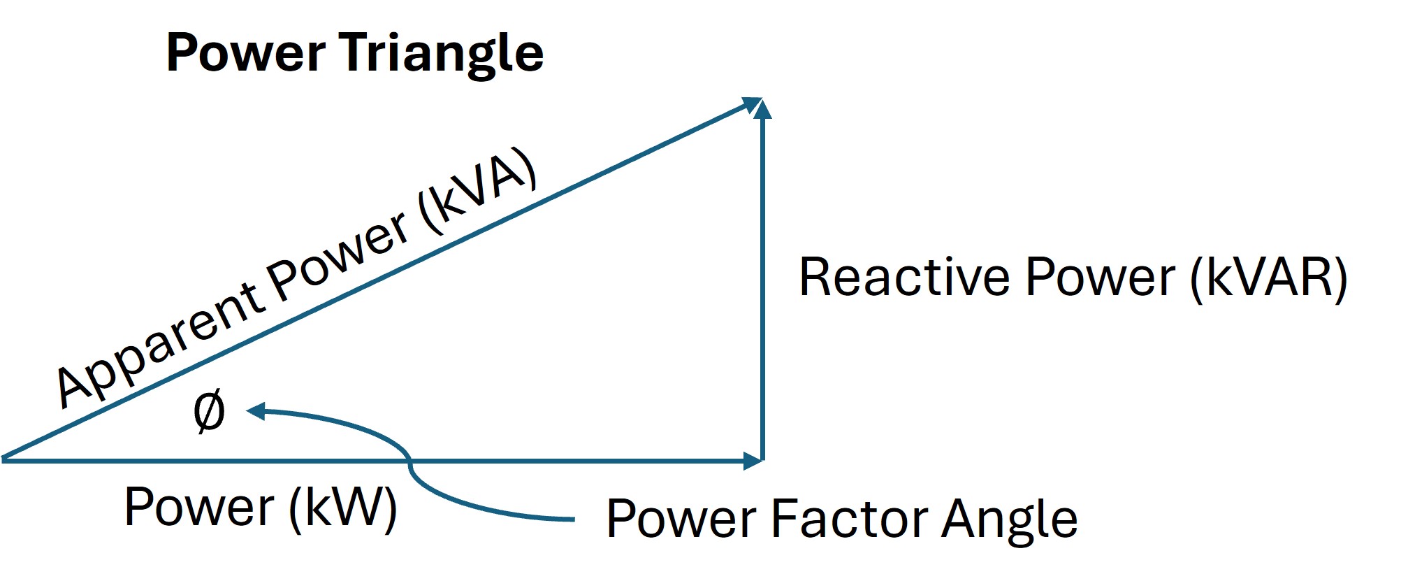
At a given system voltage, active power, reactive power, and apparent power correspond to their respective current components. The power triangle illustrates how increasing reactive power increases the apparent power and current required to deliver a given amount of active power. This relationship is fundamental to understanding power factor, electrical-system loading, and power-factor correction.
For sinusoidal operation at the fundamental frequency with negligible harmonic distortion, apparent power is calculated as:

What it calculates: Calculates apparent power (VA or kVA) from active power (W or kW) and reactive power (var or kVAR).
Engineering significance: Apparent power represents the total electrical loading imposed on the power system and is an important consideration when sizing transformers, generators, cables, switchgear, and other electrical equipment typically rated in kVA or MVA.
Total power factor (PFtotal), also called true power factor (PFtrue), is the ratio of the total active power (kW) consumed by an industrial plant to the total apparent power (kVA) supplied to the plant. It accounts for both the phase displacement between the fundamental voltage and current and the effects of harmonic current distortion.
For systems with essentially sinusoidal voltage, total power factor can be expressed as:

Where PFdist is defined as:
and THDi, the total harmonic current distortion, is defined as:
Displacement power factor is the ratio of active power of the fundamental wave to apparent power of the fundamental wave, which is equivalent to the cosine of the phase angle by which the fundamental current lags or leads the fundamental voltage. Distortion power factor is the ratio of the fundamental frequency circuit current to the total root-mean-squared line current, which decreases from unity whenever there are nonlinear loads supplied by the circuit.
The fundamental difference between these two components dictates how they must be corrected in an industrial facility. Displacement power factor can be improved by adding a source of reactive power, such as shunt power capacitors. In contrast, distortion power factor can only be improved by filtering out the harmonic currents that distort the fundamental current.

What it calculates: Calculates the total power factor as the product of displacement power factor (cos Ø) and distortion power factor (I1 / IL), where I1 is fundamental current and IL is total rms current.
Engineering significance: This equation highlights that simply adding capacitors to improve the phase angle (cos Ø) will not fully correct the total power factor if high harmonic currents (IL) are distorting the waveform.
VarStec’s Perspective:
In nearly all medium-voltage power factor correction applications, displacement power factor is the primary basis for determining the amount of reactive power compensation required by a facility. Harmonic performance is evaluated separately using established distortion metrics, including voltage THD, current THD, and TDD, together with the applicable limits of IEEE 519.
Accordingly, medium-voltage reactive compensation systems are typically designed by evaluating displacement power factor and harmonic performance as separate but interrelated engineering criteria. This approach provides a more meaningful basis for equipment sizing and system performance than relying on true power factor alone.
A power capacitor acts as a var generator by locally supplying the magnetizing (reactive) current required by inductive loads, such as motors and transformers. This local supply prevents the reactive current from having to flow from the utility generator (or source) through the transmission and distribution systems.
Because a capacitor stores electrical energy and releases it 180 degrees out-of-phase with inductive elements, its current leads the voltage by 90 degrees, while inductive current lags by 90 degrees. Placing a capacitor near an inductive load creates a local circulating exchange of reactive energy. This reduces the total current drawn from the upstream power supply.

What it calculates: Calculates the reactive power (vars) supplied by a capacitor, where V is voltage, Xc is capacitive reactance in ohms, f is frequency in Hertz, and C is capacitance in farads of the capacitor.
Engineering significance: This equation shows that the reactive power supplied by a capacitor is directly proportional to system frequency and proportional to the square of the applied voltage. For a wye-connected capacitor bank, single-phase var output is calculated using the line-to-neutral voltage across each capacitor phase. For the total three-phase var output of a balanced wye-connected capacitor bank, the equation may be expressed using the system line-to-line voltage.
A leading power factor occurs when the electrical current wave leads the voltage wave (shifted up to 90 degrees), which typically happens when capacitance dominates a circuit. It is defined as a condition where the circuit is supplying, rather than absorbing, reactive voltamperes (vars) to the system.
In phasor diagrams, a leading current lies in the upper quadrant relative to the voltage reference. While lagging power factors are typical of industrial plants due to inductive motor loads, leading power factors can occur during light load periods if large capacitor banks remain connected, causing the system voltage to rise.
VarStec Perspective: A modest leading power factor is generally not a concern by itself. The two practical questions are whether the resulting capacitive kvar causes an unacceptable voltage rise and whether the facility’s utility tariff permits leading operation.
The expected voltage rise from capacitor switching can be readily calculated and, in most applications, is less than a few percent unless the system is significantly overcompensated. If voltage remains within acceptable limits and the utility tariff does not penalize leading power factor, modest leading operation is typically acceptable.
A lagging power factor occurs when the alternating current wave lags behind the voltage wave due to the presence of inductive elements in the circuit. This condition is caused by the magnetizing current required to establish magnetic fields in motors, transformers, and solenoid-operated equipment.
Because inductive reactance opposes changes in current, the current waveform is delayed relative to the voltage waveform. The majority of industrial plant loads (such as induction motors) are inductive, resulting in a lagging power factor. This lagging current must be supplied by the utility unless corrected locally using capacitor banks, detuned capacitor banks and harmonic filter banks.
The primary benefits of improving a plant’s power factor include lower utility costs (by avoiding power-factor penalties or kVA demand charges), the release of system electrical capacity, voltage level improvement, improved voltage regulation, compliance with interconnection requirements and the reduction of system conductor power losses.
Improving the power factor reduces the overall current flow in the system. Thermally limited equipment is relieved of carrying unnecessary reactive current, and voltage regulation is improved because reactive voltage drop is reduced. Conductor losses are also lowered because current is reduced in direct proportion to power-factor improvement.
VarStec Practical Application Note: Most power factor correction projects are driven by utility economics or interconnection requirements. The primary financial drivers are typically direct power factor penalties or indirect charges based on kVA demand. Utility or grid interconnection requirements are another common reason facilities are required to maintain power factor within a specified range.
Improved voltage regulation, released system capacity, and reduced I2R losses are important ancillary benefits, but they are seldom the primary reason power factor correction equipment is added to an industrial electrical system.
The term “release of capacity” means that by improving the system power factor, the total current flow is reduced, thereby allowing additional active load to be served by the existing electrical infrastructure. This thermal relief applies to all series system components, including transformers, cables, generators, and switchgear.
Electrical distribution components are thermally limited by the amount of total current they can carry. By utilizing local capacitors to supply the reactive component of the current, the upstream system (from the capacitor application point back to the source) is relieved of carrying those vars. If a transformer or cable is running near its thermal limit, improving the power factor is often the most economical way to reduce current flow and gain capacity without upgrading expensive equipment.
Engineering Example:
If a plant has an electrical load of 10,000 kVA operating at a 70% power factor, and 4800 kvar of capacitors are added at the medium-voltage level to that system, the system power factor is improved to approximately 90%. This power-factor improvement releases approximately 28.5% of the electrical system’s capacity, meaning the existing system can now carry 28.5% more active load (at 70% power factor) without exceeding its original 10,000 kVA thermal limit.
The system capacity released through power factor correction can be calculated from the ratio of the original power factor to the corrected power factor as shown in the equation below. This calculation determines the percentage of existing kVA capacity made available for additional load.
Because kVA is the vector combination of kW and kvar, improving power factor reduces the kVA required to supply the same kW load. The resulting reduction in kVA demand effectively releases capacity in transformers, cables, switchgear, and other distribution equipment, allowing that capacity to support additional machinery or process loads.
VarStec’s Perspective: As industrial facilities grow, transformers, feeders, cables, and switchgear can approach their thermal or kVA limits. This can create a significant cost-saving opportunity: rather than immediately upgrading major electrical equipment, power factor correction may be used to reduce kVA demand and release usable capacity within the existing system.
A properly sized capacitor bank or harmonic filter bank reduces reactive power demand and system current, allowing existing transformers, feeders, and switchgear to add additional plant load. In many cases, the cost of the capacitor bank can be substantially less than the cost of upgrading the electrical distribution network, making power factor correction an effective way to defer or avoid capital expenditures while supporting continued plant growth.
Improving a lagging power factor reduces the current required to deliver the same kW load, which reduces the I×Z voltage drop across the electrical network and the service transformer’s leakage impedance.
At the most basic level, feeder voltage drop follows Ohm’s law:
ΔV = I × Z
Therefore, when power factor correction reduces current, the voltage drop between the source and the load also decreases.
In an AC power system, however, system impedance consists of both resistance R and reactance X, and voltage drop is more complex because the reactive component is 90 degrees out of phase with the resistive component. Utility systems, transformers, and many industrial feeders typically have relatively high X/R ratios, meaning the inductive reactance X is often much larger than the resistance R. As a result, the reactive component of current can have a significant influence on system voltage drop.
For a lagging load, the approximate line-to-neutral voltage drop is:
ΔV = IRcosϕ + IXsinϕ
The first term represents the voltage drop associated primarily with active-power current flowing through resistance, while the second term represents the voltage drop associated with reactive-power current flowing through reactance. In systems with a high X/R ratio, the IXsinϕ term can be a major contributor to the overall voltage drop.
As power factor approaches unity, ϕ approaches zero and sinϕ approaches zero. The reactive voltage-drop term therefore decreases toward zero. Power factor correction accomplishes this by supplying reactive power locally at or near the load, reducing the reactive current that must flow through the upstream feeder, transformer, and utility system.
The result is twofold: total current is reduced, lowering the overall I × Z voltage drop, and the reactive component of voltage drop is reduced directly by decreasing the IXsinϕ term. Because the resistive component of total source impedance is very low, the IRcosϕ component of voltage drop is also very low.
The percent voltage rise at a transformer secondary bus resulting from capacitor-bank energization can be estimated by dividing the capacitor-bank kvar rating by the transformer kVA rating and multiplying by the transformer percent impedance, as shown below. This approximation is most applicable where the transformer and upstream system impedance are predominantly reactive.
The same voltage rise can also be estimated from the available three-phase short-circuit strength of the system. In that form, the capacitor-bank kvar is divided by the three-phase short-circuit kVA, or equivalently, the capacitor-bank current is divided by the available short-circuit current.
Energizing a capacitor bank raises the system voltage, while de-energizing it lowers the voltage. A permanently connected capacitor bank therefore provides a continuous voltage boost whenever it is energized. As a VarStec rule of thumb, the voltage change associated with any single capacitor-bank switching step should generally be limited to approximately 2%. If the calculated voltage rise exceeds this value, the bank should normally be divided into multiple switched stages to limit the voltage change associated with each switching operation.
What it calculates: Estimates the percentage voltage change at a transformer secondary bus when a capacitor bank is energized or de-energized.
Engineering significance: This simple calculation allows plant and commissioning engineers to predict the expected voltage rise when a capacitor bank or harmonic filter bank is energized and the corresponding voltage drop when it is de-energized. Applying the VarStec’s rule of thumb for maximum voltage change per switching step helps maintain acceptable power quality and reduces the risk of nuisance trips or unexpected plant shutdowns.
Engineering Example: To find the voltage rise at a secondary bus where the transformer is rated 10,000 kVA with a 6% impedance, and a capacitor bank (or stage) rated 3,000 kvar is connected: % Delta V = (3000 / 10000) * 6% = 1.8% voltage rise.
Power factor improvement reduces conductor losses because electrical line losses are proportional to the square of the current, I2R. For a given active power (kW) and system voltage, current is inversely proportional to power factor. Therefore, conductor losses vary approximately inversely with the square of the power factor.
As power factor is improved, less current is required to deliver the same active power.
VarStec’s Perspective:
In industrial facilities, the economic value of reduced conductor losses alone is rarely (more closely to never) sufficient to justify the cost of power factor correction capacitors. However, the reduction in losses provides an important additional benefit, particularly in facilities with long feeders supplying large, low-power-factor loads.
On utility distribution systems, the economics can be considerably different. Distribution feeders may extend for many miles, making I2R losses a significant operating cost. In these applications, loss reduction is often an important factor in the application and economic justification of pole-mounted shunt capacitor banks.
Percent loss reduction can easily be calculated using the following formula:

What it calculates: Calculates the percentage reduction in system conductor I2R losses obtained by raising the power factor from an initial value (PFInitial) to an improved value (PFCorrected).
Engineering significance: This relationship demonstrates that improving the power factor reduces thermal energy wasted as heat in cables and feeders.
The required capacitor rating to raise the power factor of a constant active load is calculated by multiplying the load power in kilowatts by the difference between the tangent of the initial power factor angle and the tangent of the corrected power factor angle.

This calculation determines the amount of inductive reactive power, in kvar, that must be offset by capacitive reactive power to achieve the desired power factor. Power factor correction multiplier tables are also commonly used to simplify the calculation by providing a direct kvar-per-kW multiplier for a given initial and corrected power factor.
What it calculates: Calculates the capacitor rating, in kvar, required to raise the power factor of a constant-kW load from an initial value, PFInitial, to a corrected value, PFCorrected. In the equation, cos⁻¹(PFInitial) determines the initial power factor angle, ØInitial. The tangent of this angle, tan(ØInitial), represents the ratio of initial reactive power to active power, kVARInitial/kW. The same calculation is performed for the Save corrected power factor, and the difference between the two reactive-power ratios determines the kvar of capacitive compensation required.
With a scientific calculator, the calculation is straightforward and becomes routine with just a little practice.
Engineering significance: This is the fundamental engineering equation used to size power factor correction capacitor banks. It allows engineers to determine the amount of capacitive kvar required to reduce reactive power demand and raise the displacement power factor to a specified target.
The principal advantage of locating power factor correction capacitors at induction motor terminals is that the capacitors supply reactive power directly at the load. This reduces the reactive current that must be supplied through the upstream distribution system, thereby lowering feeder current, conductor losses, and voltage drop while releasing electrical-system capacity.
When the capacitor is connected on the load side of the motor contactor, as shown in (a) and (b) in the figure below, the motor starter switches the motor and capacitor together. The capacitor is therefore energized only when the motor is operating, eliminating the need for a separate capacitor switching device and reducing the overall cost of the power factor correction installation.
There is an important distinction between the two arrangements shown. In Figure (a), the capacitor is connected on the motor side of the overload relay. Because the overload relay measures the reduced line current resulting from the capacitor compensation, its setting must account for the capacitor current so that the motor remains properly protected. In Figure (b), the capacitor is connected between the contactor and the overload relay. The contactor still switches the motor and capacitor together, but the overload relay measures motor current only and therefore is not affected by the capacitor compensation.
Historically, individual motor compensation was a common and economical method of improving plant power factor, particularly before the widespread use of variable-frequency drives (VFDs). It provided localized reactive power compensation with relatively little additional switching equipment.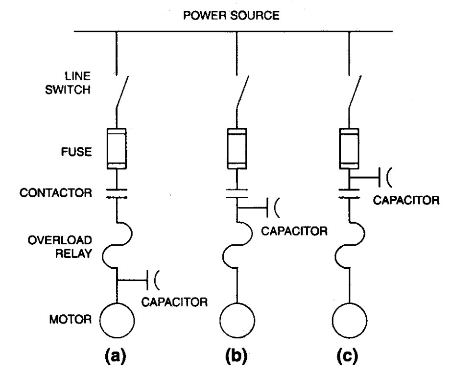
VarStec Perspective: VarStec does not recommend widespread application of individual motor capacitors in modern industrial power systems. With the increasing use of VFDs and other nonlinear loads, numerous distributed capacitors can significantly alter the system driving-point impedance and create multiple parallel-resonance conditions. These resonances may amplify harmonic currents or voltages and increase electrical stress on capacitors and other equipment.
For most modern industrial facilities, VarStec recommends applying power factor correction at the main bus or major distribution buses, where system impedance, harmonic conditions, and resonance frequencies can be evaluated as part of the overall power-system design. Centralized or strategically distributed capacitor banks also simplify switching, protection, inspection, and maintenance while typically providing a more economical long-term installation.
The economics of low-voltage versus medium-voltage power factor correction are primarily driven by current, capacitor unit size, switching equipment, and total kvar required.
At 480 V, 1 kvar requires about 1.2 A, so large low-voltage capacitor banks require substantial current-carrying equipment, including bus, conductors, fuses, and contactors. Low-voltage capacitor units are also relatively small, typically 25 to 100 kvar, resulting in more components as bank size increases.
At medium voltage, current per kvar is much lower and capacitor units are much larger, commonly 100 to 600 kvar, with some ratings up to approximately 700 kvar. This allows large banks to be built with fewer components and at a lower cost per kvar.
The trade-off is that medium-voltage switching and protection have a relatively high minimum cost. For example, a 200-A switching device at 4.16 kV corresponds to approximately 1,440 kvar, making smaller medium-voltage banks less economical.
VarStec Perspective:
As a general rule, VarStec recommends considering medium-voltage power factor correction at approximately 1,500 kvar and above. Below this level, low-voltage correction is often more economical. Above it, medium-voltage correction typically becomes more cost-effective, provided the facility has access to suitable medium-voltage switchgear or substations.
An engineering study is critical to avoid potential harmonic resonance conditions, where the capacitive reactance of the capacitor bank equals the inductive reactance of the supply transformer and power lines at a harmonic frequency generated by nonlinear loads.
If a capacitor bank is applied without analysis in a system with nonlinear loads (such as adjustable-speed drives), a parallel resonant circuit can be created. This resonant circuit will be excited by the harmonic currents generated by the nonlinear loads, causing severe voltage distortion, capacitor overheating, and fuse blowing. An engineering study determines the system’s frequency response and identifies if tuned filters are required to shift the resonant frequency to a safe harmonic.
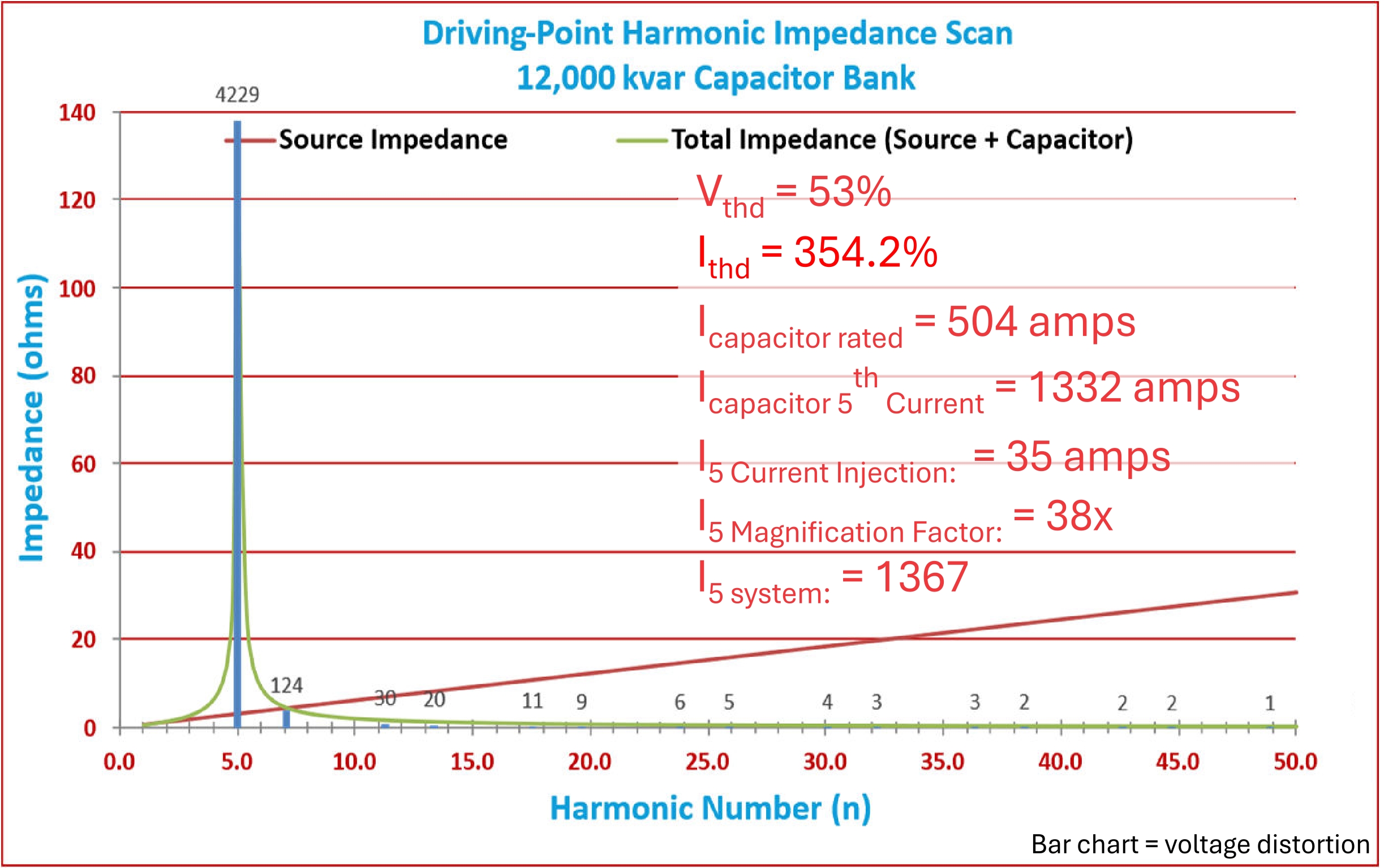
As an example, the plot shows that adding a 12,000 kvar capacitor bank on a 13.8 kV system created a resonance near the 5th harmonic, resulting in a driving point impedance near 140 ohms. With only 35 A of 5th-harmonic current injection, the resonance produced 53% voltage THD (VTHD) and 354% current THD (ITHD), demonstrating how even relatively low harmonic current can become severely amplified when a capacitor bank creates a resonant condition.
VarStec Practical Application Note: VarStec regularly performs harmonic studies using advanced power-system modeling tools to safely apply capacitor banks and custom-engineered harmonic filters in complex industrial facilities. In our experience, even relatively low levels of harmonic current can produce voltage THD well above 5% when a system resonance is present, while harmonic currents may be magnified by factors of 10 to 100, resulting in significant power-quality problems and equipment stress. The use of lower-harmonic equipment, such as high-pulse drives, does not eliminate the risk of resonance. For capacitor installations on systems with nonlinear loads, a harmonic analysis should always be performed.
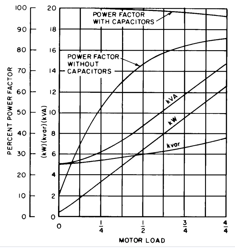
Induction motors operate at low power factors under partial loads because while the active working power (kW) decreases in proportion to the mechanical shaft load, the magnetizing reactive power (kvar) required to maintain the motor’s magnetic field remains nearly constant across the entire load range.
At no-load or light-load conditions, the motor current is composed almost entirely of magnetizing current, which lags the voltage by nearly 90 degrees. This results in an extremely low power factor (often below 30%). As the shaft load increases, the active current component increases, which raises the ratio of kW to kVA and improves the power factor (typically to 80-90% at full load). Because industrial motors are frequently oversized (over-motored) for their mechanical load, they often operate in this low-power-factor, partially loaded region.
The figure below shows typical operating characteristics for a medium-sized, medium-speed induction motor. As shown, the motor’s reactive power demand (kvar) remains relatively constant from no load through full load, while real power demand (kW) increases nearly linearly over the same load range.
If the capacitor rating exceeds the motor’s no-load magnetizing current, the motor can experience severe self-excitation overvoltages immediately after the motor starter opens. The voltage at the motor and capacitor terminals can rise to dangerous levels, causing insulation damage or capacitor dielectric failure.
When the motor starter opens, the motor continues to spin due to the inertia of its connected load. It acts as an induction generator, generating its own voltage. If the connected capacitor is oversized, it supplies more magnetizing current than the motor requires at normal operating voltage, forcing the motor’s magnetic circuit into saturation and driving the terminal voltage up to excessive levels.
Self-excitation is a phenomenon where an induction motor, disconnected from its power supply while still rotating, operates as a generator by circulating magnetizing current with a parallel-connected capacitor. This occurs because the stored mechanical energy of rotation is converted into electrical energy, and the capacitor supplies the leading reactive current necessary to excite the motor’s magnetic field.
For self-excitation to occur, the motor must be rotating, and capacitance must be connected to its terminals. The frequency of the generated voltage is determined by the speed of the rotor. The steady-state voltage is determined by the intersection of the motor’s magnetizing saturation curve and the capacitor’s voltage-current characteristic curve. In practice, the voltage will eventually decay as the motor slows down due to friction, windage, and mechanical load, but the transient overvoltage can cause immediate damage if the capacitor is oversized.
Capacitors must never be connected directly to a motor’s terminals when solid-state starters are used, when open-transition starting is employed, or when the motor is subject to repetitive switching, jogging, reversing, plugging, or high-inertia loads that can drive the motor.
In these applications, the high-frequency switching of solid-state devices can damage the capacitors, or the rapid current transitions can produce severe transient overvoltages and torques. Under these conditions, the capacitors should be connected to a separate contactor that is electrically interlocked with the motor starter, rather than wired directly to the motor leads.
Why must switching devices applied to capacitor banks be derated under the National Electrical Code?
Capacitor switching devices must be sized above the capacitor bank’s nominal current because actual operating current can exceed nameplate current under normal system conditions. Capacitors are manufactured with a positive capacitance tolerance of up to +10% in accordance with IEEE Std 18, and capacitor current also increases with system overvoltage. In addition, nonlinear loads can introduce harmonic currents that further increase the RMS current carried by the capacitor bank and its associated switching equipment.
The National Electrical Code (NEC), Article 460, requires capacitor circuit conductors, switching devices, and associated equipment to have a continuous-current rating of at least 135% of the capacitor’s rated current. This additional current-carrying capacity accommodates capacitance tolerance, normal system overvoltage, and harmonic current, helping prevent excessive heating, accelerated contact wear, and premature equipment failure.
Capacitor banks are more difficult to switch because capacitor current reaches zero when the system voltage is near its peak. When the switch contacts open, a high voltage can therefore develop very quickly across the contact gap.
If the contacts cannot withstand this voltage as they separate, the arc can re-establish, causing a restrike. Restrikes can produce high-frequency transient currents and overvoltages that place additional stress on the switching device.
For this reason, capacitor banks require switching devices specifically designed and rated for capacitor switching duty.
The physical cause is that voltage cannot change instantaneously on a capacitor. When a switch closes, a high-frequency natural-frequency transient voltage component must develop to bridge the difference between the capacitor’s pre-switching charge (typically zero) and the instantaneous system voltage at the moment of switch closing.
This natural-frequency transient component oscillates and adds to the steady-state fundamental voltage wave. Without damping, this transient can cause the total capacitor voltage to overshoot and reach up to 2.0 times the crest of the system line-to-neutral voltage. In practice, system resistance and inductance provide damping that limits the peak, but the resulting high-frequency inrush current can still range from 5 to 15 times the capacitor’s rated current.
The natural resonant frequency of a capacitor bank in combination with system impedance can be calculated using the circuit inductance and capacitance, or estimated in per-unit of the fundamental frequency as the square root of the ratio of system short-circuit MVA to the capacitor bank MVAR rating.
This resonant frequency represents the frequency at which the inductive reactance of the system equals the capacitive reactance of the capacitor bank. Knowing this frequency is critical to ensure that system resonances do not align with any characteristic harmonics produced by nonlinear loads.
The transient restrike phenomenon occurs when a switching device attempts to interrupt capacitive current but experiences a dielectric breakdown across its opening contacts half a cycle after the initial current zero, when the voltage across the contacts has reached twice the system crest voltage.
When capacitive current is interrupted at current zero, the capacitor is left with a trapped charge equal to the peak system voltage (e.g., +1.0 per unit). Half a cycle later, the system voltage swings to its opposite peak (-1.0 per unit), resulting in a potential of 2.0 per unit across the open switch contacts. If the switch restrikes at this moment, a high-frequency transient oscillation is initiated that overshoots the system voltage, potentially driving the capacitor terminal voltage to 3.0 times its normal peak, with even higher values possible on subsequent restrikes.
VarStec Practical Application Note: VarStec specifies and installs vacuum circuit breakers and high-performance switches with superior capacitance switching ratings to eliminate the risk of restrikes and dangerous overvoltages.
Zero-voltage control is a controlled-switching technique that times capacitor switch closure so the voltage difference across the switch contacts is at or near zero at the instant of energization. For an uncharged capacitor, this generally means closing as the AC system voltage passes through zero. By minimizing the voltage applied across the capacitor at the moment of switching, the resulting energization transient is significantly reduced.
Under ideal zero-voltage switching conditions, the natural-frequency transient component can be theoretically eliminated. This greatly reduces high-frequency inrush current and transient voltage overshoot, thereby lowering electrical and mechanical stress on the capacitor bank and switching device. The result is reduced stress on capacitor elements, longer switch contact life, and less electromagnetic interference with nearby control and electronic equipment.
VarStec Note: When harmonic filter banks are used, zero-voltage closing is generally not required because the filter tuning reactor inherently limits and damps capacitor energization transients.
Related Technical Topics
VarStec’s Medium-Voltage Power Factor Correction Expertise
VarStec specializes in medium-voltage power factor correction applications from 2.4 kV through 38 kV, providing metal-enclosed capacitor banks and harmonic filter banks engineered for reliable performance in real-world power systems. Our solutions are applied across a wide range of industries, including oil and gas, data centers, commercial facilities, industrial plants, and mining.
With more than 30 years of practical experience in capacitor bank and harmonic filter bank design, application, and manufacturing, VarStec develops systems to address utility interconnection requirements, voltage support objectives, power factor penalties, and kVA-based utility billing structures. Where harmonics are present, VarStec also applies harmonic filter bank solutions to support both power factor correction and harmonic mitigation, helping ensure the equipment is properly matched to the operating characteristics of the system.