
Protecting medium-voltage metal-enclosed capacitor banks and harmonic filter banks requires more than simple overcurrent detection. Effective protection typically combines current-limiting fuses, blown-fuse detection, unbalance protection, overcurrent and overvoltage protection, VTHD and ITHD monitoring, resonance protection, fan-failure monitoring, thermal-overload protection, and properly coordinated control logic to limit equipment damage, remove failed stages, or shut down equipment before cascading problems develop.
Guided by IEEE C37.99, IEEE 18, IEEE 1036, and IEEE 1531, and drawing on more than 30 years of practical experience in the design, manufacture, protection, testing, and commissioning of medium-voltage capacitor banks and harmonic filter banks, VarStec develops System-Fit™ protection schemes tailored to the specific bank configuration, electrical system, operating duty, and application. This Technical Q&A chapter addresses practical questions involving capacitor fusing, direct blown-fuse sensing, neutral unbalance protection, relay and fuse coordination, overload and overvoltage protection, resonance, harmonic distortion, thermal overload protection, and protection-setting philosophy for medium-voltage capacitor banks and harmonic filter banks.
Capacitor Bank & Harmonic Filter Bank Protection Technical Q&A
How do I protect compact medium-voltage metal-enclosed capacitor banks against fuse thermal failure?
Direct blown fuse detection with thermal actuation is required to protect metal-enclosed capacitor banks from fuse thermal failure. Traditional indirect unbalance schemes detect capacitance loss but cannot identify a fuse operating in its prohibited thermal overload zone. To ensure robust protection:
- Specify Direct Sensing: Utilize microswitch monitoring assemblies mounted directly on the fuse. Such systems are available from SIBA.
- Require Thermal Actuation: Ensure the fuse is equipped with a thermal actuator and striker pin.
- Coordinate with Indirect Schemes: Use direct sensing as the primary protection, with split-wye neutral current unbalance as a secondary backup.
Per IEEE C37.99, failure to clear thermal overloads can result in severe enclosure damage. For comprehensive protection solutions, review our technical documentation in our engineering briefs.
VarStec Recommendation: Always specify direct fuse sensing with thermal actuation in metal-enclosed capacitor banks and harmonic filter banks.
Split-wye neutral current detection is generally preferred over single-wye neutral voltage detection because it provides a more direct and inherently stable indication of capacitor-bank unbalance. By dividing the bank into two electrically symmetrical wye sections and measuring the current between their neutrals, the scheme responds primarily to an internal difference between the two sections—such as that caused by a blown fuse or failed capacitor unit.
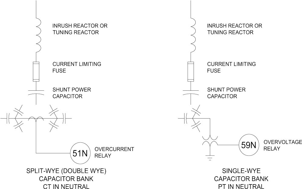
Unlike a single-wye neutral-voltage scheme, split-wye neutral current detection does not require a neutral voltage transformer (PT/VT). This avoids the insulation, switching-duty, and Transient Recovery Voltage (TRV) application concerns associated with neutral voltage transformers. It also reduces susceptibility to false operation caused by external system conditions. As discussed in IEEE C37.99-2012, neutral-voltage schemes can respond to neutral displacement produced by remote line-to-ground faults or system phase-voltage unbalance, whereas a properly designed split-wye differential neutral-current scheme largely rejects these common-mode effects.
VarStec Practical Application Tip:
Where the capacitor-bank configuration permits it, VarStec generally prefers a split-wye neutral current unbalance scheme for sensitive blown-fuse detection and capacitor-bank protection because it provides reliable detection of internal bank unbalance while minimizing the influence of external system disturbances.
Unbalance protection should trip and lock out the capacitor bank before the voltage across any remaining healthy capacitor unit exceeds 110% of its rated RMS voltage. Loss of capacitor units or elements changes the voltage distribution within the affected series group, causing the remaining units to operate at progressively higher voltage. If additional units fail, this overvoltage can accelerate dielectric deterioration and lead to a cascading capacitor-unit failure.
The unbalance trip setting should therefore be established from the calculated voltage rise associated with successive fuse operations or capacitor-unit failures:
Calculate the contingency voltage: Determine the voltage imposed on the remaining healthy capacitor units after each successive fuse operation or unit failure.
Identify the critical failure level: Determine the number of failed units or elements that causes the voltage on the remaining units to exceed the 110% rated RMS voltage limit.
Set the trip threshold: Establish the protective trip setting between the signal corresponding to the last acceptable contingency and the next contingency that would exceed the allowable voltage. Where practical, setting the threshold approximately midway between these two discrete unbalance levels provides operating margin.
Establish an alarm level: Set an alarm below the trip threshold so that an initial fuse operation or developing bank unbalance can be identified and corrected before the bank reaches the protective trip level.
IEEE Std 18 establishes the allowable capacitor operating-voltage limits that must be considered when determining the unbalance protection setting. The 110% capability should not be treated as a normal design operating point; the bank should be designed to operate near rated voltage with adequate margin for system overvoltage and contingency conditions.
VarStec Practical Application Tip:
Set the unbalance protection so that the bank is removed from service before the next credible fuse operation or capacitor failure would drive any remaining unit above 110% of rated RMS voltage. The VarStec C37.99 Unbalance Calculator can be used to determine the corresponding alarm and trip thresholds for the specific bank topology.
Harmonic filter banks are generally configured to trip and lock out on the first detected blown fuse because the loss of even one capacitor unit changes the filter’s effective capacitance and therefore its tuning frequency. Unlike a conventional power-factor correction capacitor bank, a harmonic filter is designed around a specific relationship between capacitance and inductance, so operating with a degraded capacitor section can materially change the filter’s electrical behavior and performance.
When a capacitor unit or element is lost, the effective capacitance of the affected filter branch decreases. Filter tuning frequency is inversely proportional to the square root of the product of inductance and capacitance, as shown below.

Accordingly, a reduction in capacitance shifts the tuning frequency upward. Depending on the filter design and system impedance, this shift can:
- Move the filter closer to a dominant harmonic such as the 5th harmonic.
- Increase harmonic current through the remaining capacitors and reactor.
- Produce excessive capacitor voltage and reactor thermal stress.
- Create or aggravate a parallel resonance with the upstream power system.
- Cause rapid escalation from a single fuse operation to additional capacitor or reactor failures.
For this reason, the acceptable degraded-operation philosophy used for some conventional capacitor banks should not automatically be applied to harmonic filters. The protection must account not only for capacitor-unit overvoltage, but also for the change in tuning, resulting harmonic duty on the filter components, and its performance.
VarStec Practical Application Tip:
For harmonic filter banks, VarStec recommends configuring the unbalance protection to trip and lock out the affected filter stage on the first detected fuse operation, unless a detailed harmonic and protection study demonstrates that continued operation with the specified contingency is safe.
To learn more about harmonic filter tuning and its impact on filter performance and reliability, see VarStec Engineering Brief VEB-006: Medium-Voltage Harmonic Filter Design: Engineering for Reliability.
An ungrounded-wye configuration should be selected first and foremost to prevent zero-sequence harmonic currents from entering the ground path and to strictly limit fault-current magnitude during a capacitor-unit failure. For industrial systems, those two characteristics are major reasons ungrounded-wye and split ungrounded-wye arrangements are so widely used.
Several factors should be considered when selecting the capacitor-bank connection:
- Zero-sequence harmonic isolation: An ungrounded-wye bank does not provide a direct neutral-to-ground path for zero-sequence currents. This helps prevent triplen harmonic currents from flowing through the capacitor-bank neutral and grounding system, where they can contribute to interference, unwanted relay operation, and other grounding-system problems.
- Fault-current limitation: With the capacitor-bank neutral isolated from ground, the current associated with an internal capacitor-unit-to-ground fault is inherently limited compared with a solidly grounded-wye arrangement. This reduces fault duty and helps contain the consequences of a capacitor failure.
- System grounding: On an ungrounded or resistance-grounded power system, the capacitor bank must be configured as ungrounded-wye or split ungrounded-wye. Grounding the capacitor-bank neutral would create an unintended low-impedance zero-sequence path and fundamentally alter the grounding characteristics of the system.
- Protection philosophy: Ungrounded-wye and split ungrounded-wye arrangements are particularly well suited to sensitive unbalance protection schemes for blown-fuse and capacitor-unit failure detection.
VarStec Practical Application Recommendation:
For most industrial metal-enclosed capacitor banks and harmonic filter banks, VarStec generally uses an ungrounded-wye or split ungrounded-wye configuration because it blocks zero-sequence current paths, limits internal ground-fault current, and provides an effective basis for sensitive unbalance protection. On ungrounded and resistance-grounded systems, the ungrounded connection is mandatory.
Canadian Utility Application Note:
An important exception occurs on many Canadian utility distribution systems, where multi-grounded-neutral systems operating at approximately 25 kV to 27.6 kV are common. On these systems, grounded-wye capacitor banks are frequently selected because each phase is referenced to ground, allowing economical single-phase vacuum switches to operate within their phase-to-ground voltage capability.
Capacitor-bank unbalance protection must be coordinated with the capacitor-unit fuse so that the fuse is allowed to completely clear and isolate the failed capacitor unit before the bank switching device trips.
While the capacitor unit is in a failed state (before fuse operation), such as when one or more internal series sections of a capacitor have shorted, the resulting change in capacitance creates a measurable capacitor-bank unbalance that is detected by the unbalance relay. The relay should recognize this condition immediately, but its trip time delay must be long enough to allow the capacitor-unit fuse to fully operate and isolate the failed unit before the bank breaker or switch opens.
That distinction is important: the relay does not have to wait for the fuse to blow to detect the unbalance; it detects the capacitor failure itself. The intentional delay is there to give the fuse time to clear first.
If the capacitor-bank switching device trips before the capacitor-unit fuse has fully cleared, several protection and operational problems can result:
- No positive blown-fuse indication: If the capacitor-bank breaker or switch opens before the capacitor fuse has fully cleared, the failed capacitor unit may not produce a visible blown-fuse indication, such as a pop-up indicator.
- Potential reuse of a damaged fuse: The fuse may remain physically intact even though it has been stressed or partially damaged by fault current. If it is inadvertently returned to service, it may fail unpredictably during a future event.
- Risk of misdiagnosing the trip: If maintenance personnel inspect the bank and find no visibly blown fuse, they may interpret the unbalance relay operation as a false or nuisance trip.
- Risk of re-energizing a failed unit: Personnel may then attempt to re-energize the capacitor bank while the failed capacitor unit is still connected, creating the potential for additional damage or a more severe failure.
For this reason, the protection sequence should be deliberate: allow the capacitor-unit fuse to fully operate and positively isolate the failed unit first, then allow the unbalance relay to trip and lock out the capacitor bank. The relay time delay should therefore be coordinated with the fuse manufacturer’s maximum total-clearing time, with sufficient margin to ensure reliable fuse operation before the bank switching device opens.
To coordinate the protection:
- Determine maximum fuse clearing time: Use the fuse manufacturer’s published time-current characteristics and identify the maximum total clearing time for the maximum and minimum fault-current conditions applicable to the capacitor unit.
- Coordinate the unbalance trip delay: Set the unbalance protection delay longer than the maximum expected fuse total-clearing time, including appropriate margin for fuse tolerances, relay accuracy, and operating conditions.
- Provide clearing margin: A coordination margin of approximately 0.05 to 0.10 seconds beyond the slowest credible fuse-clearing time is commonly appropriate, provided it remains within the allowable capacitor-unit overvoltage and bank protection limits.
- Verify the complete protection sequence: Confirm that the fuse clears first, the resulting unbalance is detected, and the bank then trips and locks out if the unbalance exceeds the established protective threshold.
VarStec Practical Application Tip:
Do not set capacitor-bank unbalance protection solely for the fastest possible response. The correct objective is selective operation: capacitor-unit fuse first, bank trip second. Always coordinate the relay delay against the actual fuse manufacturer’s maximum total-clearing curve for the specific fuse.
Harmonic-filter protection must address conditions that conventional capacitor-bank protection may not detect, particularly harmonic overload, detuning, and resonance. VarStec recommends a layered approach that includes:
Harmonic-current protection: Monitor total RMS current, ITHD, and significant individual harmonic currents such as I5, I7, I11, and I13. Conventional 50/51 protection may respond primarily to fundamental-frequency current and therefore should not be relied upon as the sole protection against harmonic overload.
Coordinated alarm and trip settings: Establish settings from the harmonic study with adequate margin above expected operating levels but below the current, voltage, and thermal capability of the filter components. This provides protection without unnecessary nuisance trips.
Voltage-distortion and resonance protection: Continuously monitor VTHD and ITHD and significant individual harmonic voltages. Abnormal increases can indicate filter detuning, capacitor-unit degradation, changes in system impedance, or the development of a resonant condition. Alarm and trip thresholds should be coordinated with the equipment design and system study.
Reactor over-temperature protection: Consider equipping harmonic-filter reactors with temperature monitoring or thermal switches, where practical, to detect abnormal heating caused by excessive harmonic current, overload, restricted airflow, or developing reactor problems. Floating-core filter reactor designs can be particularly difficult to monitor reliably with conventional thermal sensors or thermocouples, and may require specialized temperature-monitoring equipment.
Enclosure over-temperature and fan-failure protection: For enclosed harmonic-filter systems that rely on forced ventilation, enclosure temperature should be monitored and ventilation fans supervised. A failed fan, blocked filter, or loss of airflow can cause internal temperatures to rise rapidly, so high-temperature alarm and trip functions should be provided to protect capacitors, reactors, resistors, and other internal components.
Because harmonic-filter protection is not fully addressed by conventional capacitor-bank protection requirements, the protection philosophy should be based on the harmonic study, filter component ratings, expected operating conditions, and potential future changes to the power system.
Thermal overload protection must be applied independently to filter reactors and capacitors, recognizing that they fail under different stress mechanisms and have distinct thermal characteristics. VarStec recommends the following practices to safeguard these critical components:
- Reactor Thermal Overload (IRMS and 49 Protection): Sustained harmonic-current duty increases reactor losses and I2R heating and, under severe conditions, can drive iron-core reactors toward magnetic saturation, resulting in excessive temperature rise, increased noise and vibration, insulation deterioration, and eventual reactor failure. Traditional branch fuses are intended primarily for short-circuit protection and generally do not provide adequate protection against sustained thermal overload. Likewise, conventional 50/51 overcurrent elements are not specifically designed to protect against the cumulative heating effects of harmonic currents and may not accurately represent the reactor’s total RMS current and thermal stress. VarStec recommends applying true-RMS current monitoring with 49 thermal-overload protection, supplemented where appropriate by current THD (ITHD) and individual harmonic-current monitoring, to ensure that the reactor remains within its continuous current, harmonic-current, and thermal design limits.
- Reactor Thermal Time Constant Delay: Because medium-voltage reactors are physically massive and have long thermal time constants, typically 1 to 2 hours, they do not overheat instantaneously. Reaching near steady-state temperature can require roughly four thermal time constants, or approximately 4 to 8 hours. Therefore, VarStec recommends setting reactor overload trips (such as IRMS or ITHD) with a time delay of several minutes. This prevents nuisance tripping during brief, non-damaging transient overloads while ensuring positive shutdown if a sustained overload persists.
- Direct Winding Temperature Sensing (Fiber Optics vs. Thermistors): Many engineering specifications call for low-voltage thermistors or RTDs to be embedded directly within the reactor windings. VarStec strongly advises against this practice. Medium-voltage reactors use a floating core design elevated on standoff insulators, meaning the windings operate at high system voltages (such as 15 kV or 38 kV). Embedding a low-voltage grounded wire inside a medium-voltage winding creates a dangerous dielectric hazard, degrades insulation over time, and presents an arc-flash hazard for technicians working in the low-voltage control panel. It will also cause the equipment to fail factory partial discharge. Instead, if direct temperature monitoring is mandatory, VarStec recommends utilizing fiber-optic temperature sensors, which are made of non-conductive glass and safely isolate high voltage from the controls.
- Capacitor Thermal and Overvoltage Protection: Unlike reactors, which fail from current-driven thermal heating, capacitors fail primarily due to voltage stress. Sustained harmonic currents passing through a capacitor’s reactance create a proportional harmonic voltage rise. VarStec protects capacitors by using the stage power quality meter to monitor VRMS, VTHD, and individual harmonic voltages, ensuring the combined fundamental and harmonic voltage remains below standard allowable limits.
- Resistor Thermal Overload Protection: For high-pass (HP), C-high-pass (C-HP), and H-type filters, resistors must also be protected from sustained overload. VarStec recommends installing current transformers (CTs) directly on the resistors to monitor true RMS current and applying a 49 RMS thermal overload relay. Furthermore, VarStec’s standard design philosophy is to double the calculated kilowatt (kW) rating of the resistor to build in a significant thermal margin.
Because standard protection relays filter out harmonics and are inadequate for monitoring filter duty, selecting the right protection relay and instrumentation is critical. VarStec recommends the following guidelines for protection equipment:
- Advanced Power Quality Meters: Comprehensive protection should feature advanced, multifunction power quality (PQ) meters capable of measuring up to the 50th (or 63rd) harmonic. VarStec’s preferred device is the Schweitzer SEL-735 advanced power quality meter.
- Integration and Monitoring: A separate PQ meter should be applied to each individual filter stage for large, process critical filters, to monitor stage-specific ITHD, IRMS, individual harmonic currents, and reactive power (VARs). These meters should integrate with a central programmable logic controller (PLC) to manage overall bank operations and safety interlocks.
- Communication and Diagnostics: Protective relays should be able to communicate with plant control and monitoring systems using common protocols such as Modbus or IEC 61850. They should also record operating data and the sequence of events when a trip or abnormal condition occurs. This information allows engineers to remotely determine what happened, when it happened, and what caused the event.
- Factory Testing: VarStec recommends that all protection relays be fully programmed, configured, and secondary/primary injection tested by the manufacturer at the factory before shipment, verifying exact trip settings using injected harmonic currents and voltages.
Group fusing provides overcurrent and short-circuit protection for an entire capacitor stage or bank, but it does not provide reliable protection for an individual failing capacitor unit.
A capacitor can develop an internal fault that draws enough current to cause overheating, gas generation, and increasing internal pressure while still drawing too little current to operate the group fuse. Because the group fuse responds to the total current of the stage, a relatively small fault in one capacitor may remain undetected until the capacitor fails more severely. For this reason, group fusing should primarily be considered stage-level short-circuit protection, rather than protection against individual capacitor-unit failure.
VarStec Practical Application Note: VarStec generally considers group fusing appropriate only where available fault current is high and the fuse is intentionally applied to reduce the downstream short-circuit level. Group fuses should not be relied upon to protect individual capacitor units from low-level internal faults or developing capacitor failures.
Related Technical Topics
VarStec’s Integrated Protection & Control Approach
VarStec provides complete protection and control systems as part of its medium-voltage metal-enclosed capacitor banks and harmonic filter banks. These systems are engineered as part of the overall equipment design, with protective devices, control logic, and settings selected to match the specific bank configuration and application. Prior to shipment, all protection and control devices are set and tested at the factory to support efficient field installation, start-up, and commissioning. With more than 30 years of experience in the design, manufacturing, and commissioning of medium-voltage metal-enclosed capacitor banks and harmonic filter banks, VarStec applies practical field experience and applicable IEEE standards, including IEEE C37.99, IEEE-18-2025, IEEE 1036-2020, and IEEE 1531-2020, to develop System-Fit™ solutions for reliable operation and long-term equipment performance.