
Harmonic analysis is fundamental to the reliable application of capacitor banks and harmonic filters in industrial and medium-voltage power systems. This Technical Q&A explains the core concepts engineers need to evaluate harmonic behavior, including IEEE 519 limits at the point of common coupling (PCC), THD versus TDD, system impedance and harmonic resonance, harmonic measurements, capacitor-bank interactions, and passive harmonic filter design. Drawing on extensive practical experience in power-system analysis, capacitor-bank application, and harmonic filter design, VarStec combines first-principles engineering, field measurement review, and computer modeling to identify resonance risk, evaluate harmonic performance, and develop System-Fit™ solutions for power factor correction and harmonic mitigation.
Harmonic Analysis Fundamentals Technical Q&A
No. In VarStec’s view, not every capacitor bank application requires a detailed computer-based harmonic analysis to identify risk. In many cases, basic engineering calculations are enough to determine whether adding capacitance could create resonance near characteristic harmonic frequencies already present in the plant.
The real issue is harmonic resonance. If even low levels of background harmonics are present, and the added capacitor bank creates resonance near one of those harmonic frequencies, the resulting amplification can drive voltage distortion above commonly referenced levels such as 5% VTHD. When that happens, IEEE 519 current distortion limits at the point of common coupling are also often exceeded.
This can occur even with so-called “IEEE 519 compliant” drives, high-pulse drives, or active front-end drives. Low harmonic current does not eliminate the problem. If the system is resonant near a frequency produced by the drive, even a small harmonic source can be amplified to an unacceptable level.
For that reason, if a plant has low-level background harmonics and resonance is possible near those frequencies, VarStec recommends detuned capacitor banks, typically tuned near 4.0 to 4.2, or toward a true harmonic filter tuned near a characteristic harmonic such as the 5th.
Detailed computer-based harmonic analysis is more appropriately used for harmonic filter design and for evaluating expected filter performance on complex systems, or on complex non-linear loads, not as the only way to recognize resonance risk in a capacitor bank application.
IEEE 519 applies two different types of limits at the PCC. Voltage distortion limits are intended to ensure the utility is providing reasonably clean voltage. Current distortion limits, usually expressed as total demand distortion (TDD), limit how much harmonic current the customer can push back onto the utility system.
The allowable current distortion, based on the harmonic current limits presented in IEEE 519, depends on system strength at the PCC as well as the voltage level. A stronger, stiffer system with higher available short-circuit current can tolerate more harmonic current because it produces less resulting voltage distortion, while higher PCC voltage levels are subject to more restrictive limits.
The Point of Common Coupling (PCC) defines the boundary of responsibility between the utility and the industrial user by acting as the specific interface point in the power system where the limits of IEEE 519-2022 are enforced.
- The Point of Common Coupling (PCC) is defined as the point on the public power supply system, electrically nearest to a particular load, at which other loads are, or could be, connected. It is located upstream of the load being evaluated.
- For an industrial user supplied through a dedicated service transformer, the PCC is frequently taken at the high-voltage (HV) side of the transformer. For commercial users supplied through a common service transformer, the PCC is commonly at the low-voltage (LV) side of the transformer.
VarStec’s Perspective: VarStec cautions engineers against applying IEEE 519-2022 current limits to individual pieces of equipment or to internal branch feeders within a plant. This is a frequent point of confusion: a variable frequency drive (VFD) manufacturer may market a drive as “IEEE 519 Compliant” but IEEE 519 limits are defined strictly at the PCC, not at individual loads. Internal plant buses often exhibit much higher distortion levels due to local resonance or a lack of load diversity. As currents propagate upstream toward the PCC, harmonic cancellation and load diversity naturally mitigate the net distortion. Therefore, compliance must always be measured and modeled at the utility interface.
A notch filter is a sharply tuned filter designed to trap one specific harmonic. A damped high-pass filter is a broader filter designed not only to filter harmonics, but also to damp resonance and control a wider range of frequencies above and below its tuning point.
A notch filter is the simplest harmonic filter. It consists of a power capacitor bank and an inductor tuned so that, at the selected harmonic frequency, the capacitive reactance equals the inductive reactance. At that tuning point, the filter presents very low impedance to the harmonic source, so harmonic current is drawn into the filter very effectively. Its impedance characteristic is very sharp, like a narrow “V,” with the bottom of the curve near zero ohms. But at nearby frequencies, the impedance rises quickly, so its filtering effect is highly selective.
A damped filter can be either a high-pass filter or a C-high-pass filter. In both cases, a resistor is added to broaden and flatten the impedance characteristic near the tuning region. Instead of a sharp “V,” the response becomes more like a shallow “U.” The amount of damping depends on the resistor value. This broader response makes the filter less selective than a notch filter and not able to filter as well at its tuning point, but much better at controlling resonance and attenuating a wider band of harmonics.
It is called a damped filter because it is often used to damp resonant conditions, including resonance between filter branches in a multi-tuned bank, or resonance involving system capacitance such as cable capacitance or other shunt capacitor banks on the network.
Yes, if the measurements are being used to establish baseline harmonic current injection data for a harmonic study. Energized capacitor banks, and harmonic filter banks, can distort the measured results and make them unsuitable for building an accurate system model.
A proper study must identify the actual harmonic current being injected into the system. If measurements are taken upstream of the capacitor bank connection point, such as at the secondary main for a system-wide assessment, while capacitor banks are energized, the data will reflect harmonic currents that have already been amplified or attenuated by the system. That is not true source-current data and can lead to an inaccurate model.
Engineering Tip:
Make sure the study engineer receives measurements that represent actual harmonic current injection, not modified values due to attenuation or amplification.
For measurements taken at the main incoming, or anywhere upstream of the capacitor bank connection point, capacitor banks should be turned off, even if only for a few minutes. This is often the single most important step in obtaining useful harmonic measurement data.
If the capacitor banks cannot be turned off because of operating constraints or power factor penalty concerns, measurements should be taken only downstream of the capacitor bank connection point, such as on feeders serving individual drives or other harmonic-producing loads. This usually requires more measurement points and increases cost.
For harmonic studies, good results depend not just on taking measurements, but on taking them in the right locations.
To understand the difference between Total Harmonic Distortion (THD) and Total Demand Distortion (TDD) as defined by IEEE 519-2022, one must look at how each metric is referenced to evaluate waveform distortion.
- Total Harmonic Distortion (THD) is defined as the ratio of the root-mean-square (RMS) of the harmonic content (considering components up to the 50th order and specifically excluding interharmonics) expressed as a percentage of the fundamental frequency component.
- Total Demand Distortion (TDD), on the other hand, is the ratio of the RMS of the harmonic content (also up to the 50th order and excluding interharmonics) expressed as a percentage of the maximum demand load current (IL) under normal operating conditions. IEEE 519 specifies that the demand interval must be either a 15-minute or 30-minute period.
VarStec’s Perspective: This distinction is critical because evaluating current distortion and compliance to IEEE solely via THD can be highly misleading. During light-load periods, the fundamental current component is small; consequently, even a minor harmonic current injection can yield an alarmingly high THD percentage. TDD prevents this distortion “inflation” by referencing the harmonics to the maximum demand current (IL), ensuring that limits are evaluated against the true capacity of the electrical system. VarStec highlights that IEEE 519-2022 current limits are strictly specified in TDD because it provides a stable and realistic baseline for system capacity evaluations, preventing unnecessary alarms when a facility is running at minimal load.
To evaluate the numerator of real-time current and voltage distortion under IEEE 519-2022, the standard defines a nested hierarchy of shorter-term statistical measurement intervals instead of using the static 15-minute or 30-minute demand period. Because power system harmonics fluctuate dynamically with changing plant loads and grid conditions, these statistical windows ensure compliance is assessed over short, medium, and long durations.
The standard structures these measurement windows as follows:
- The Basic Measurement Window (12/10 Cycles): The foundational digital processing window uses a Discrete Fourier Transform (DFT) width of 12 cycles (approximately 200 ms) for 60 Hz systems, or 10 cycles for 50 Hz systems. This window combines the center harmonic frequency with its two adjacent 5 Hz bins to define a single RMS harmonic magnitude.
- Very Short-Time Measurements (3-Second Window): Calculated by aggregating 15 consecutive basic 12-cycle (or 10-cycle) windows using an RMS calculation.
- Short-Time Measurements (10-Minute Window): Calculated by aggregating 200 consecutive very short-time (3-second) values using an RMS calculation.
Statistical Compliance Limits
Once collected, these measurements are accumulated over defined evaluation periods (1 day for very short-time and 7 days for short-time) and compared against the standard’s current and voltage limit tables using strict percentile thresholds:
- Daily 99th Percentile (Very Short-Time / 3-Second): Evaluated over each 24-hour period.
- Current Distortion Limit: The measured 3-second current harmonics must remain below 2.0 times the nominal Table limits.
- Voltage Distortion Limit: The measured 3-second voltage harmonics must remain below 1.5 times the Table 1 limits.
- Weekly 99th Percentile (Short-Time / 10-Minute): Evaluated over each 7-day period.
- Current Distortion Limit: The measured 10-minute current harmonics must remain below 1.5 times the nominal Table limits.
- Weekly 95th Percentile (Short-Time / 10-Minute): Evaluated over each 7-day period.
- Current Distortion Limit: The measured 10-minute current harmonics must remain below 1.0 times the nominal limit.
- Voltage Distortion Limit: The measured 10-minute voltage harmonics must remain below 1.0 times the Table 1 limits.
Adding a standard capacitor bank to a power system with non-linear loads creates a risk of parallel resonance because the capacitive reactance of the capacitor bank acts in parallel with the inductive reactance of the utility source transformer.
- At a specific frequency, known as the resonance point, the inductive reactance of the source and capacitive reactances of the capacitor bank become equal and opposite, causing the total parallel system impedance to spike to a very high value. See the figure below.
- When non-linear loads inject harmonic currents near or this resonant frequency, the high parallel impedance multiplied by the non-linear load harmonic current in amps, resulting in high voltage distortion. This can operate capacitor fuses, trigger nuisance overvoltage trips, cause premature capacitor dielectric failure, power quality issues through-out the plant, and non-compliance with IEEE 519-2022.
VarStec’s Perspective: To avoid this destructive parallel resonance, VarStec recommends converting standard power factor correction capacitor banks into tuned notch harmonic filters or detuned capacitor banks by adding series iron-core tuning reactors. By choosing a tuning frequency below the dominant harmonic (typically around the 4.7th harmonic for a 5th harmonic source), the series reactor “pegs” the parallel resonance point so that it falls safely below the 5th harmonic. Because there are no major harmonic sources below the 5th harmonic, the resonant peak is bypassed, and the filter provides a safe, low-impedance path to ground for the dominant 5th harmonic current.
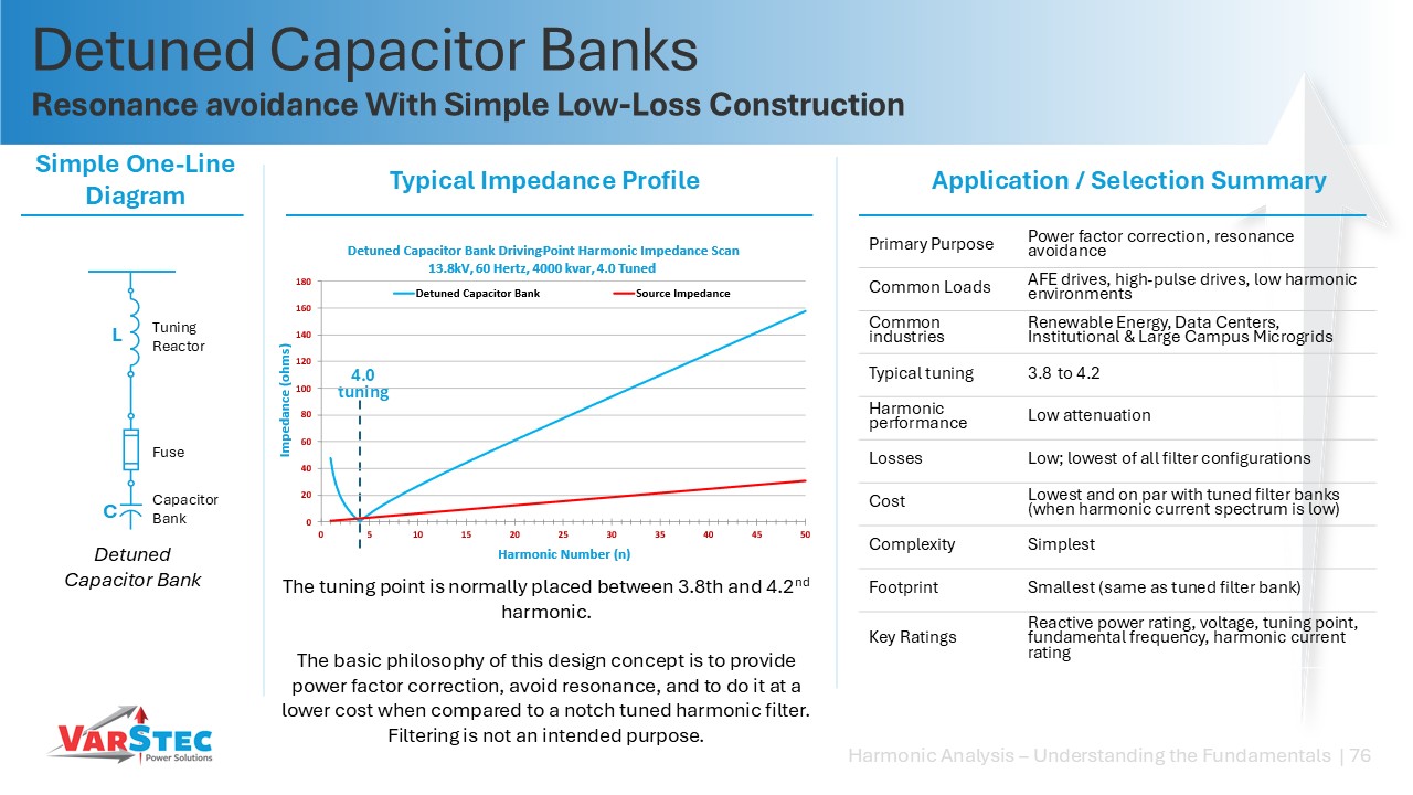
A “detuned capacitor bank” (typically utilizing a 6% reactor to achieve a 4.08 tuning point) is a capacitor bank that uses an iron-core reactor designed primarily for power factor correction and resonance avoidance, rather than active harmonic filtering.
- A 6% series reactor is added to the capacitor bank to tune the LC circuit to approximately the 4.08th harmonic in a 60 Hz system.
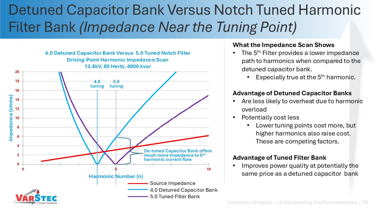
- The fundamental philosophy is to shift the bank’s resonant frequency safely away from the dominant 5th harmonic so that the filter impedance at the 5th is sufficiently high to minimize the absorption of harmonic currents, while also keeping the anti-resonance point well below the 5th.
VarStec’s Perspective: VarStec generally advises against standard detuned capacitor banks in environments with high harmonic distortion. While detuned banks are marketed as a way to avoid harmonic filter overload without needing a full harmonic study, they are actually just current dividers. Because the impedance of a 4.08-tuned bank is still relatively low compared to the utility source impedance at the 5th harmonic, a significant portion of the 5th harmonic current will still flow into the detuned bank. As a result, detuned capacitor banks are still highly susceptible to thermal overloads. VarStec recommends utilizing properly designed tuned notch filters (typically tuned to the 4.7th harmonic). If there is a risk of overloading the stage, rather than detuning it further away from the problem harmonic, engineers should design the filter components with the proper rating, with conservative margins so that they can safely absorb and mitigate the system’s harmonics.
The voltage ratings of capacitors in a harmonic filter must be rated significantly higher than the nominal system line-to-neutral voltage due to two compounding voltage rise phenomena.
- Fundamental Voltage Rise: Because a tuning reactor is placed in series with the capacitor bank, the inductive reactance (jXL) and capacitive reactance (-jXC) oppose one another. At the fundamental frequency (50 or 60 Hz), this series opposition creates a continuous fundamental voltage rise across the capacitor terminals, calculated in the formula noted below. n is the tuning point of the filter, VLN is the line-to-neutral voltage rating of the system where the filter is being installed, and Vrise is the voltage rise on the capacitor.

- Harmonic Voltage Rise: Harmonic currents flowing into the harmonic filter branch produce a secondary harmonic voltage drop across the capacitor’s reactance(Vh = Ih x XC(h) ) which adds vectorially to the fundamental voltage.
VarStec’s Perspective: To ensure a robust service life, VarStec’s design philosophy is to strictly calculate capacitor voltage requirements utilizing a dedicated filter design spreadsheet tool that models worst-case system overvoltage (110% of nominal) plus the absolute maximum harmonic current injection. For example, on a standard 13.8 kV system (where nominal line-to-neutral voltage is 7.96 kV), applying a standard 7.96 kV capacitor will result in immediate overvoltage stress and premature failure. VarStec recommends specifying a capacitor rated for at least 9.54 kV or 9.96 kV, and ensuring that the selected unit is rated as heavy-duty (HD) or extra heavy-duty (EHD) in accordance with IEEE 18 standard ratings.
In a multi-stage notch filter system, the staging sequence is highly critical because the parallel anti-resonance peaks of the filter branches are dynamically determined by which stages are currently online.
- To avoid introducing severe transient resonances, multi-tuned branches must always be staged in a strict sequence, starting from the lowest harmonic order (typically the 5th) and moving upward (e.g., 5th, then 7th, then 11th).
- If a lower-order stage (such as the 5th harmonic filter) trips offline while higher-order stages (the 7th or 11th filters) remain energized, the parallel resonant peak of the remaining higher-order stages will shift.
VarStec’s Perspective: VarStec warns that a lower-stage outage presents a severe cascading reliability risk. For example, if the 5th tuned filter is taken offline in a 5th, 7th, 11th, multi-tuned filter bank, the parallel resonant peak of the remaining 7th harmonic filter is highly likely to shift directly over the 5th harmonic frequency. Because the 5th harmonic is very often a predominate harmonic order, this resonance shift creates a resonance that will instantly overload and damage the remaining 7th and 11th harmonic filters. Consequently, VarStec’s standard control philosophy dictates that if a lower-order filter stage (like the 5th) suffers an outage, the control system must automatically and immediately trip all higher-order filter stages (the 7th, 11th, etc.) offline to prevent catastrophic cascading failures.
For this reason, multi-tuned filters should only be specified when single tuned 5th filters cannot meet system performance requirements. The multi-tuned filter provides better filtering performance, but at the cost of reliability.
To control resonance peaks across a broad frequency spectrum, damped high-pass, C-type high-pass, and H-type harmonic filters utilize damping resistors connected in parallel with the tuning reactors.
- The resistor acts as a energy-absorbing bypass path. At the tuning frequency and above, the reactor’s impedance increases (+jXL), forcing higher-frequency harmonic currents to divert through the parallel resistor. This flattens the filter’s impedance curve, effectively damping out high-order parallel resonance peaks that can occur due to stray system or cable capacitance.
- However, the primary trade-off of a standard High-Pass (HP) filter is that fundamental-frequency (50/60 Hz) current continuously passes through the damping resistor, resulting in substantial, continuous I2R power losses that increase operating costs. To mitigate these losses, a C-High-Pass (C-HP) filter introduces an auxiliary capacitor (Caux) in series with the resistor. The auxiliary capacitor and the tuning reactor are tuned precisely to the fundamental frequency, forming a zero-impedance bypass around the damping resistor. This prevents fundamental-frequency current from entering the resistor, reducing continuous losses to near-zero.
- An H-Type double-tuned damped filter provides a similar high-efficiency configuration that targets two discrete tuning points while maintaining excellent damping with low fundamental losses. Trip-tuned H-Type filters are also available from VarStec Power Solutions, Inc.
VarStec’s Perspective: While standard HP filters are simpler, the annual operating cost of their continuous losses can be massive. VarStec recommends C-HP and H-Type configurations for applications requiring high levels of damping, such as wind farms with extensive underground cable capacitance
or industrial plants with cycloconverters and arc furnaces as they provide the necessary resonance protection without sacrificing system efficiency.
Measuring harmonics on the secondary of a transformer with online capacitor banks is misleading because the capacitors alter the total impedance of the network, creating a parallel resonant circuit, which results in current magnifciation or attenuation that distorts the true non-linear load being measured.
- When a capacitor bank is online, the load’s harmonic current injection is amplified or attenuated by the parallel LC loop formed by the bank and the source transformer.
- Therefore, a current probe placed on the transformer secondary will measure the sum of the load’s actual injection and the amplified or attenuated resonant currents circulating within the LC loop, rather than the true harmonic output of the nonlinear loads.
VarStec’s Perspective: To obtain accurate, baseline harmonic data for a filter design study, VarStec recommends two primary measurement guidelines:
- Switch off all capacitor banks and filters before performing harmonic measurements on a transformer secondary. This isolates the nonlinear loads and ensures that the captured current spectrum represents pure load injection, undistorted by local resonance.
- If the capacitor banks cannot be taken offline due to voltage stability or power factor penalties, measurements must be taken directly at each individual nonlinear load feeder (i.e., at the VFD or rectifier input).
Even when capacitor banks are offline, VarStec notes that cable capacitance must still be considered as a potential factor for high-order harmonic distortion, making direct load-side measurements the gold standard
Related Technical Topics
VarStec’s Practical Approach to Harmonic Analysis and Filter Application
VarStec applies practical engineering experience to the analysis of harmonic behavior in medium-voltage power systems and the design and manufacture of metal-enclosed capacitor banks and harmonic filter banks. Our work includes system modeling, field measurement review, resonance evaluation, and the development of system-fit™ solutions for power factor correction and harmonic mitigation. Guided by applicable industry standards and grounded in first-principles engineering, our approach is focused on equipment that is properly applied, technically sound, and aligned with the power quality and reliability objectives of the project.